Is it really 2–50 UPR? Don’t be so sure!
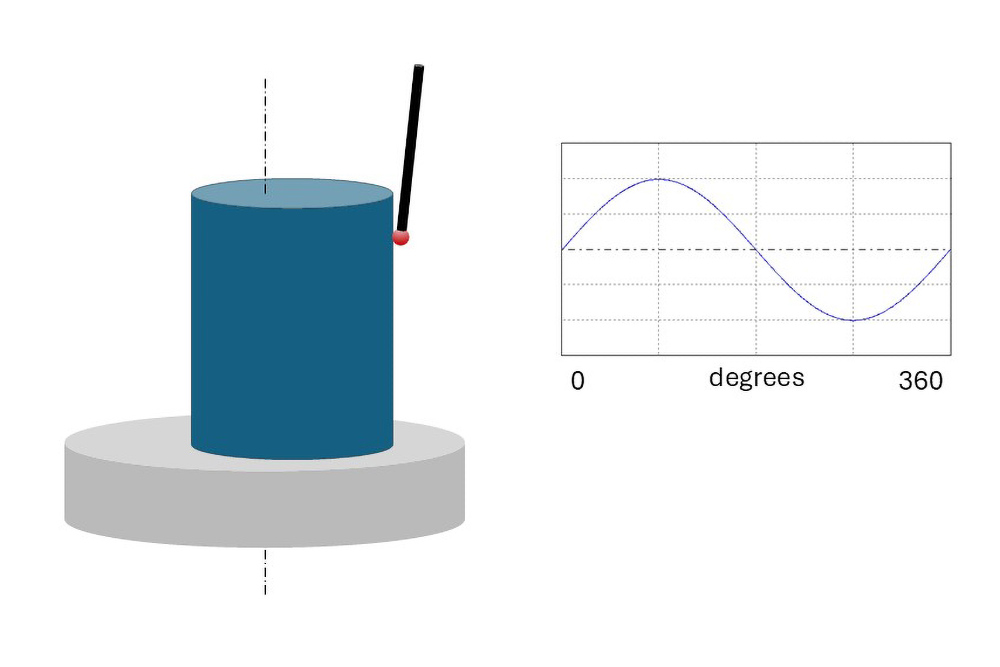
Whether rolling, sliding, sealing, or simply fitting together, round geometries are everywhere. And controlling the shape of these “ideally round” surfaces is critical to their performance. Historically, roundness has been specified and controlled as what can be described as “waviness around a circle.” Higher frequencies are “filtered out” to reveal the underlying trends of the surface. The process is similar to how filtering out surface roughness can reveal waviness.

Traditionally, a default filter cutoff frequency of 50 undulations per revolution (UPR) has been applied to “filter” or “smooth” out higher frequencies which likely won’t impact part performance. However, recent efforts in both standards and in industry may be changing that. A newer approach is to vary the filter cutoff frequency with the part size in order to maintain a similar cutoff wavelength with roughness analysis. With this approach, the short circumferential wavelengths (high frequencies) are considered as roughness and the long circumferential wavelengths (low frequencies) are considered as roundness (i.e., waviness).
In any case, the calculation of roundness is typically based on a filtered dataset which removes high frequencies like roughness. And in the majority of cases a 50 UPR roundness filter is used.
A bit of background on roundness filtering
If we base our roundness analysis on a 50 UPR cutoff frequency, we tend to think that the low frequency shapes on the left side of the image below will be included in our analysis, while the higher frequency shapes to the right will be filtered out.
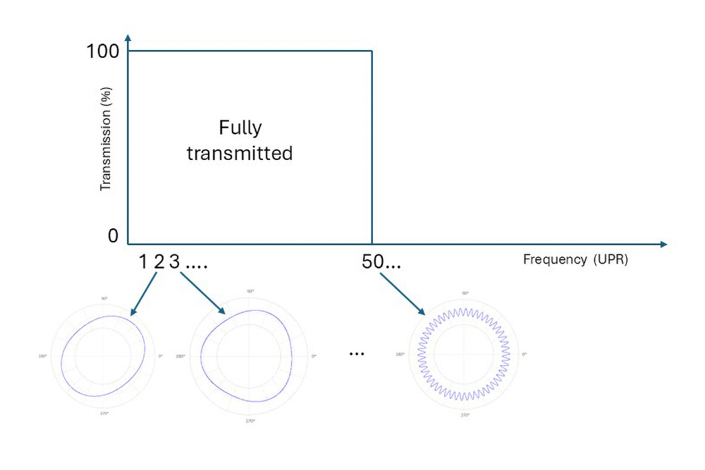
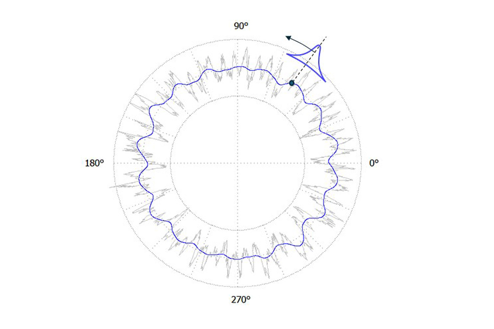
However, this isn’t the case. The figure represents a “Fourier” or “Brickwall” filter transmission. This type of filter can cause artificial “ripples” in the filtered data – due to the nature of sinewaves , and those artificial ripples could lead to a misleading representation of the surface.
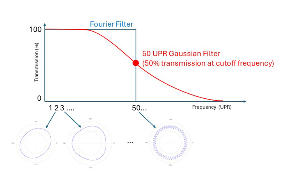
A Gaussian filter is a better option. The Gaussian filter is based on smoothing the data with a Gaussian (bell curve shaped) moving average, as in the image below. The Gaussian filter provides the sharpest possible transmission, without causing distortions (or “ripples”) in the smoothed data.
However, the Gaussian transmission is not nearly as steep as the Brickwall filter. The frequencies near to the cutoff frequencies will be attenuated to varying degrees rather than simply being passed or removed. In fact, a 50 UPR Gaussian filter only transmits 50% of the amplitude at 50 UPR whereas the Brickwall filter transmits 100%.
Where does roundness start?
Let’s think about the frequencies of roundness. Ovality is a 2nd order surface error and a tri-lobed part has a 3rd order surface error.
But the first order can cause us to make a mistake. First order errors are due to the surface not being aligned with a spindle or datum.
Since first order shape is due to alignment, not workpiece roundness, many people apply a 2–50 UPR filter to remove that first order effect as well as the frequencies above 50 UPR.
The issue with a 2–50 UPR specification
There’s a nuance here that has caused many problems in industry. Here is the ideal case for the transmission of frequencies with a 50 UPR roundness filter:
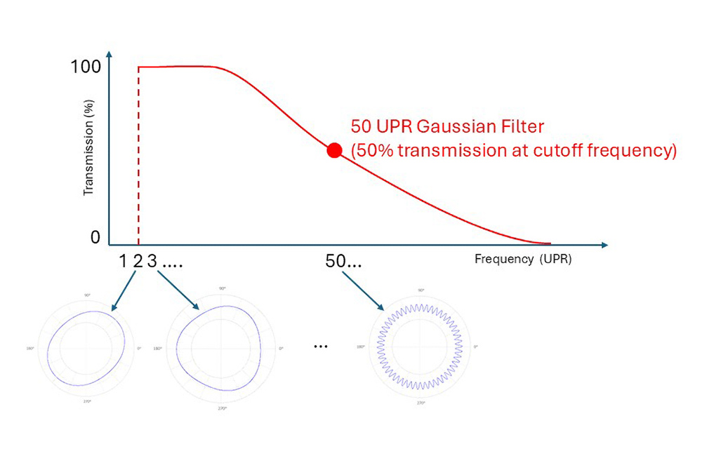
The first order error is handled by the fitting of a reference circle. The rest of the frequencies are controlled by the single, selected filter. But when we specify a 2–50 UPR filter, many measuring systems interpret this as a bandpass analysis made up of two filters, one at 2 UPR, and one at 50 UPR.
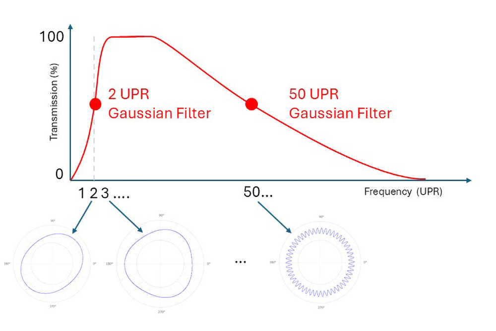
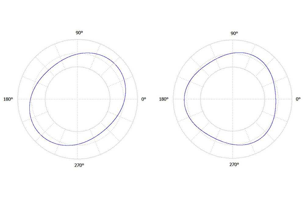
This can lead to very misleading results! The filter placed at 2 UPR is only transmitting 50% of the ovality. In other words, if your part is oval, you will only see half of the ovality! Important, neighboring frequencies like 3 UPR and 4 UPR will also be attenuated (often by a lot!), simply because of how the instrument interprets the 2–50 UPR specification.
Is there a better way to specify roundness?
It’s important to note that not all measurement systems will implement the 2–50 filter this way. Some may overrule you. Your measuring systems user’s manual or help system may provide guidance on the subject.
That said, in most cases, it’s simply safer to apply only one filter cutoff value… not two. By choosing only the roundness cutoff value (e.g., 50 UPR or whatever frequency is specified), the instrument’s reference circle fitting will automatically take care of the first order for you. Your result will be based on a single filter as you intended.
For more information regarding specifying and measuring roundness, reach out to us!