Can I trust my measurement?
Asking that question every time we measure drives us to be careful—and that keeps us producing meaningful results.
Let’s look at a “simple” shop floor measurement of surface finish, made with a skidded instrument. And, let’s explore something that you might not imagine: “upward” dirt on the surface can cause “downward” errors in the surface measurement.
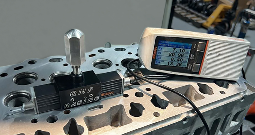
Photo Credit: Matthew Hussey
“Skidded” vs “skidless”
To review, in a “skidless” stylus system, the stylus swings to follow the surface shapes as the measurement unit moves across the surface. The stylus is free to capture all of the wavelengths of the surface: form, waviness, and roughness. A skidless stylus, however, is exposed. Debris, large steps, fast transitions, etc., can all damage or destroy the stylus tip. A skidless system is also VERY sensitive to vibrations that are common on a shop floor.
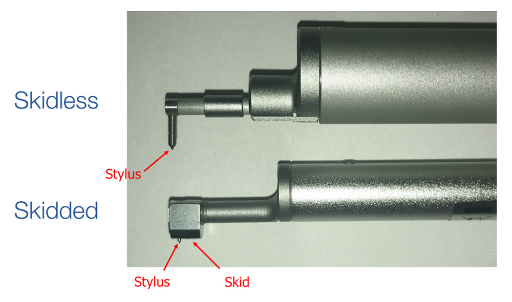
Skidless and skidded stylus (Courtesy The Surface Texture Answer Book).
A “skidded” system includes a radiused skid that rests on the surface along with the stylus. The skid provides a reference while the stylus moves relative to it.
Skidded stylus (Courtesy The Surface Texture Answer Book).
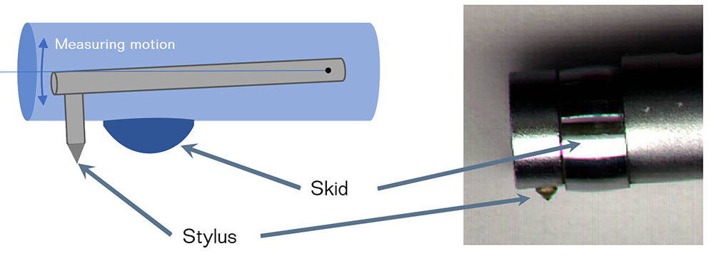
The skid follows the larger shape of the surface while the stylus detects the short wavelength roughness. A skidded stylus is therefore somewhat protected from larger-scale texture, making it more suitable to face the rigors of production measurement. The tradeoff is that the skid “filters out” the longer wavelength form and waviness because the movement of the stylus is always relative to the skid. That tradeoff is often worth it for production roughness measurements, so most of the stylus systems we encounter are skidded.
What happens when the skid and stylus encounter dirt?
When the skid rises up on debris, the stylus extends farther down to stay in contact with the surface. That extra extension results in an artificial “dip” in the measured profile, as in the image below. If the stylus also passes over the debris, a sharp peak will be created along with the dip.
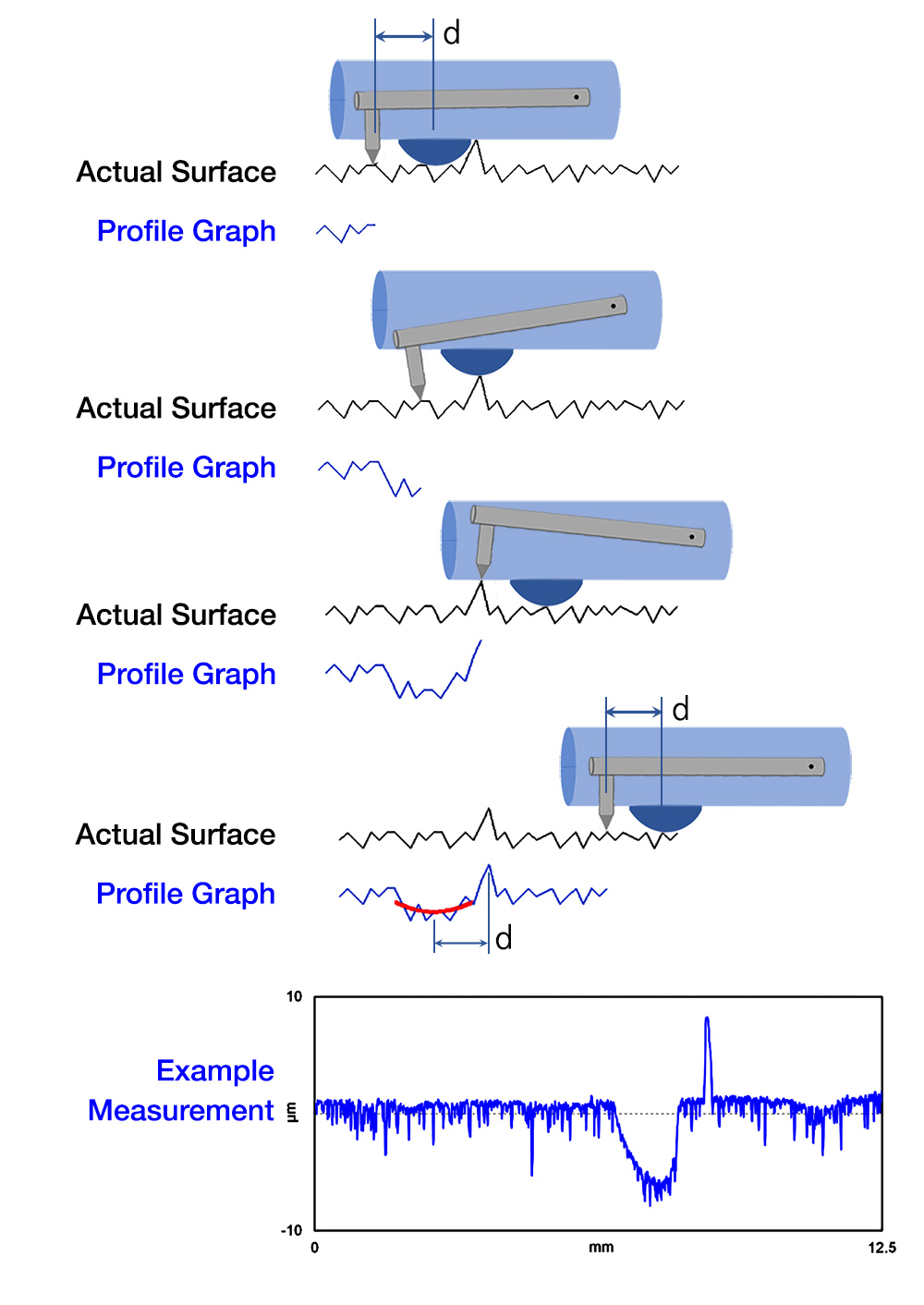
Profile when the skid and stylus pass over debris. Courtesy The Surface Texture Answer Book.
This kind of errors (a dip accompanied by a sharp peak) can be indicative of the stylus encountering dirt.
What happens when the skid encounters dirt, but the stylus does not?
A skid is typically much wider than the stylus, so it is much more likely that the skid will encounter debris while the stylus will miss it. In this case, the result is a dip in the profile data without a corresponding peak, as in the image below. These types of errors are more common but are harder to spot because they look like naturally occurring valleys.
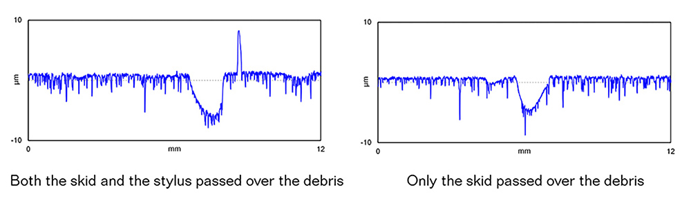
Profiles created when the skid and stylus pass over debris (left), and when the skid passed over debris but the stylus misses it (right). Courtesy The Surface Texture Answer Book.
How does this affect my parameters?
It may seem counterintuitive that a parameter measured on a skidded system (which is robust against vibration) could have a higher value than a measurement from skidless instruments. The reason is that on a dirty surface, the artificial dips, caused by the skid rising onto debris, may not be adequately removed by the roughness filter.
In the image below, the skid has passed over debris while the stylus has missed it. The result is an artificial dip, as we saw above. The debris does not appear in the profile graph because the stylus tip missed the debris.
On the left, with the roughness cutoff set to 2.5mm, the artificial dip passes into the roughness profile, results in a higher roughness value. Note that the filter “falling into” the artificial valley also introduces artificial peaks on either side of the valley, further increasing the roughness value. On the right side of the figure, a shorter roughness cutoff has been applied. Now, the artificial dip is almost completely absent in the roughness profile, providing a more representative roughness value.
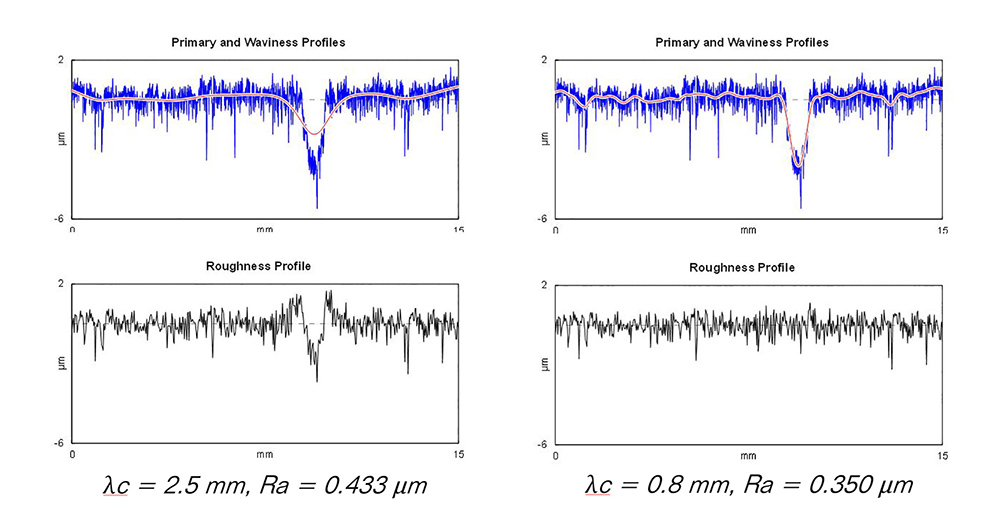
Effect of cutoff on the roughness value from a skidded stylus tracing over debris (Courtesy The Surface Texture Answer Book).
So, what do we do when we see unexpected valleys?
Knowing whether the valleys on a surface are real or artificial is critical to knowing what to do next. If your process has changed in some way, then you’ll need to apply corrective measures. If the features are artificial, however, you could be chasing your tail trying to solve a problem that is not really there.
The first solution is always to clean the surface again and remeasure. Several error-free measurements over the same region should indicate that the valleys in the first measurement were caused by debris.
Another option is to look at the raw profile, or even the primary profile, which will often provide some clues. For example, if we are making a plateaued surface, the honing valleys will be relatively narrow while skid-induced errors will be comparatively wider. In addition, a skid-induced “dip” may still show some of that plateau shape, particularly along the bottom of the dip.
Want to know more about stylus measurements and the kinds of errors you may encounter? The Surface Texture Answer Book goes into detail on the subject, and many other aspects of surface measurement. Check it out!