The ASME Y14.5 standard is a foundation for geometric dimensioning and tolerancing (GD&T) around the world. It provides methods for communicating part sizes, geometries, orientations, and positions. The primary language of Y14.5 is centered around concept of zones and “fit.”
But what if “fit” isn’t the function we are working with?
When we’re talking about functions such as sealing, friction, appearance, etc., many of the Y14.5 the tools may still be helpful, but they aren’t optimal.
The new Y14.49 supplemental specification gives us new tools to better specify these “non-fit” functions.
Case Study 1 – The Brake Rotor Problem
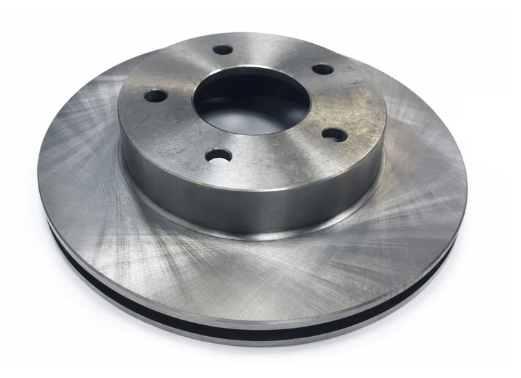
Let’s consider the face of a brake rotor. This critical surface contacts the brake pad, so the shape of the face impacts braking and overall safety. We need to control the flatness of the braking surface for the rotor-to-pad interface to do its job.
The term “flatness” captures the deviations of a surface relative to a perfect plane. We often see pictures like this in the description of flatness. 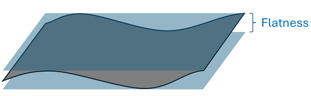
ASME 14.5-2018, Section 4.1 fundamental rule “S” further elaborates on this concept. It states that we need to capture all surface elements – including surface texture and flaws.
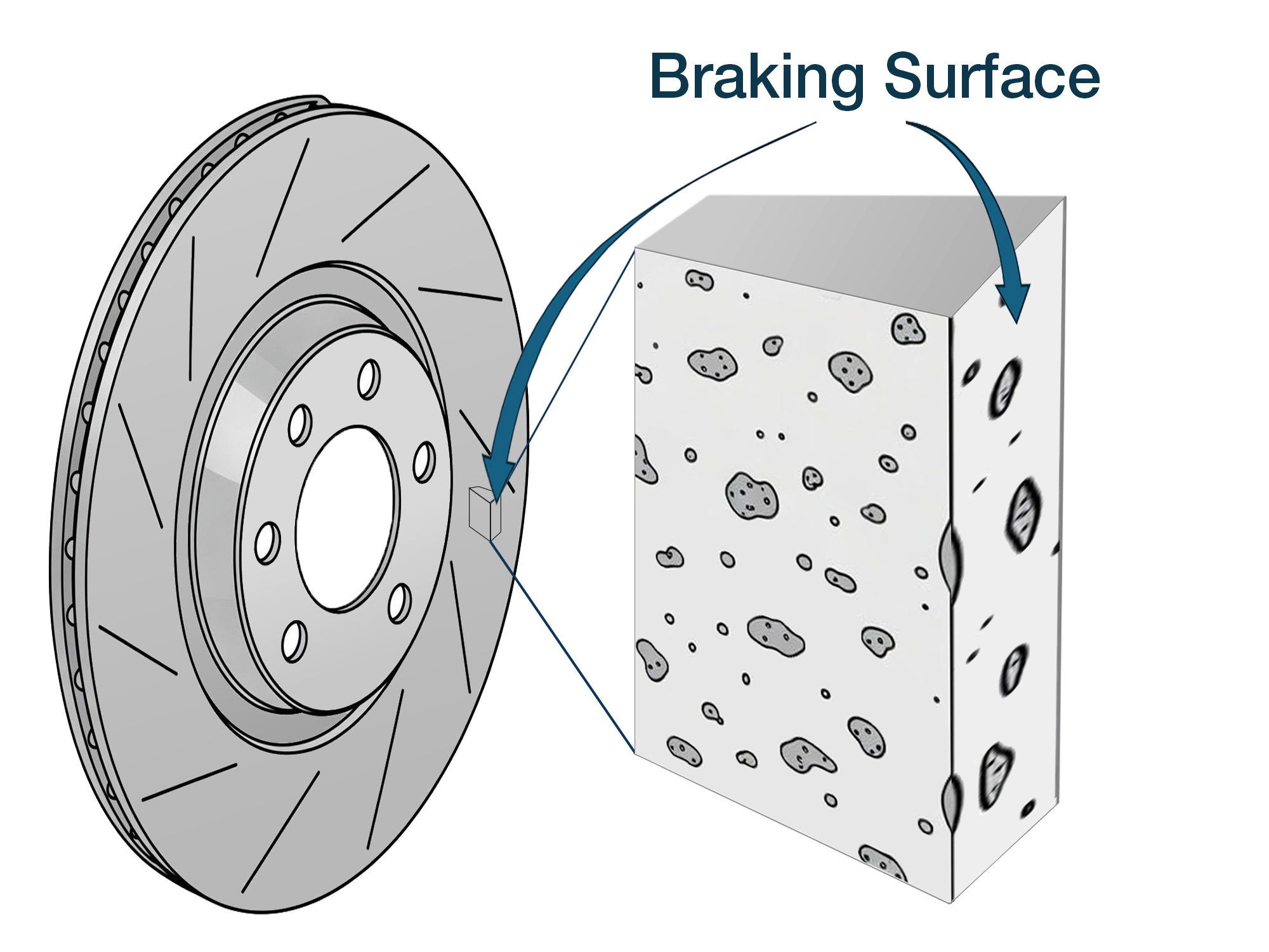
While this might look like the kind of control we need for brake rotors, it does not always translate well for real world parts. Brake rotors are often made with relatively rough surface textures that will eventually wear away. They also commonly have very deep porosity (a type of “flaw), with pores that are typically much deeper than that required flatness control.
Here’s an actual measurement of a braking surface at the scale required by ASME Y14.5-2018 (4.1 ‘S’) which includes surface texture and flaws:
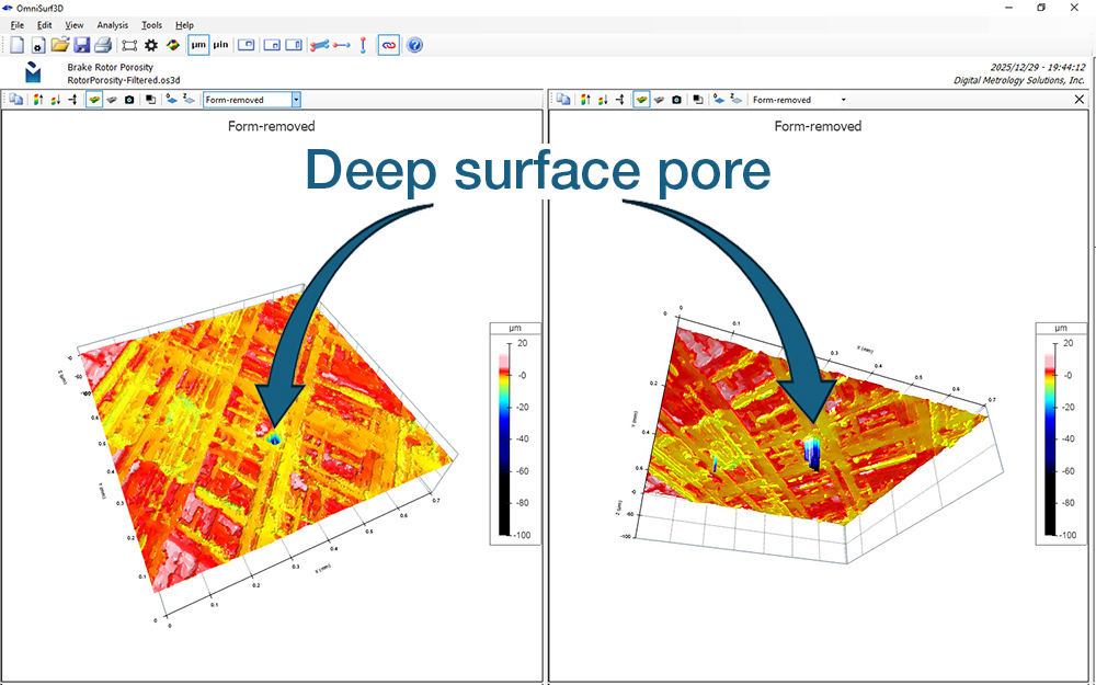
The deep pores in this measurement will not impact braking performance because the pad never touches them. The functional flatness—the flatness that the brake pad will “feel” during braking—is only affected by the “upper” surface which contacts the pad. The porosity does not affect function at all. What’s more, those extreme roughness peaks will immediately be worn away with the first application of the brakes!
The porosity does, however, have a huge impact on the flatness per the ASME Y14.5 definition, since the pores are often much deeper than the flatness tolerance.
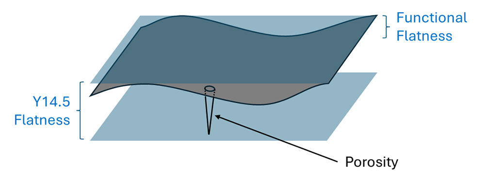
So, if we want to define the “functional” flatness of the rotor, we need a way to include underlying trends in the upper surface and exclude the deep pores.
How the ASME Y14.49 standard can help
ASME Y14.49 allows us to refine the definition of the functional surface we want to control. Let’s describe it in words first.
- For flatness, we only care about the long wavelengths.
- Short-wavelength, deep features (such as porosity) will not affect the braking.
- Narrow (roughness) peaks are not significant as they will be worn away in the first few seconds of use.
- We care about the entire braking surface that will contact the pad.
- We need to control the total (peak-to-valley) deviations of that functional surface.
Here’s how flatness has traditionally been specified:
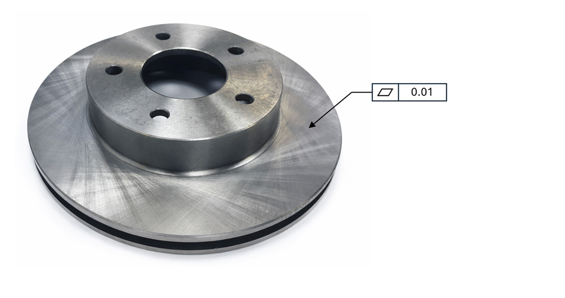
This (above) traditional callout indicates an upper limit on overall flatness of 0.01 mm, or 10 µm. If we follow ASME Y14.5 and include the porosity, we will reject most rotors, even though they will be fully functional.
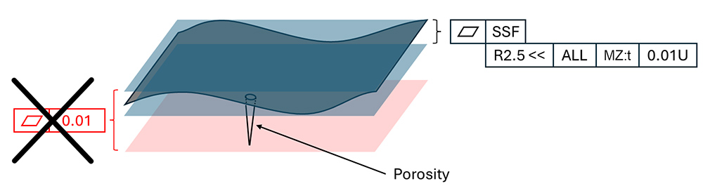
ASME Y14.49 defines a “Supplemental Specification Frame” (SSF) to enhance the flatness callout and address the functional requirements we listed above and to make sure we’re only assessing the shapes that we care about:

Let’s look at each piece of the frame:
Filter type and limits. The first block specifies the type of filter (e.g., Gaussian, Robust, etc.) and the cutoff wavelengths for each.
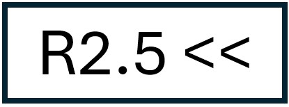
For the brake rotor, we will apply a Robust (“R”) short filter, to suppress the roughness (i.e., wavelengths smaller than 2.5 mm.) “<<”indicates that there is no upper filter limit; we want to include all of the long wavelengths as they will be felt by the brake pads. We are using a robust filter type as it is best suited for extreme, outlying features like porosity.
Evaluation extent. The evaluation extent is determined by the geometric characteristic of the surface. For flatness, the evaluation extent could be an area of a defined size, or it could be ALL of the surface, as in this case.

Controlled quantity. This is the particular parameter that needs to be controlled. In this case, we are controlling “t,” the “total” or “peak-to-valley” flatness, and we are evaluating it against a Minimum Zone reference like we used in the figures above.

Tolerance specification. The last box states the limits on the controlled quantity. Here, we see the upper (“U”) limit on overall flatness of 0.01 mm, or 10 µm.

The supplemental frame gives part designers a way to communicate which surface shapes matter for the application. This is a well defined geometric characteristic that can be clearly communicated, measured and tracked.
Over the next few weeks, we’ll add more examples to show how Y14.49 will help with specifying and analyzing surface texture. Stay tuned!
If you have any questions regarding Y14.49 and how to interpret the new SSF, or would like training on this new standard – contact us! We’d be glad to help.