The calibration of roundness measuring systems is often misunderstood and misapplied. There are several factor at play here. Let’s take a look at the basic concepts and shed some light on this.
Let’s start with the language…
First off, the term “calibrate” is not properly used in the world of roundness. The word “calibrate” basically means “determine what you have; as compared to the proper value.” Gage blocks are calibrated.
In roundness measuring systems we often see the word “Calibrate” or the word “Calibration” to refer to the process of “adjusting” the system. Technically, this isn’t the correct use of the word “calibration” – the proper word is “adjustment” or “correction.”
For the sake of this discussion, I’ll try to keep the concepts clear between the two.
One other bit of terminology…
The roundness measuring sensor has two parts. The electronic part that senses motion (the “probe”) and the shaft/contact that touches the part (the “stylus”). These two things work in combination with the spindle in order to make a roundness measurement. So let’s go…
What are all these things that came with my roundness gage?
Typical roundness systems come with a few extra things that can help with calibration and/or adjustment. Instruments may come with things such as:
- a precision sphere/hemisphere,
- a flick/dynamic calibration standard
- an optical flat with gage blocks.
Precision sphere/hemisphere
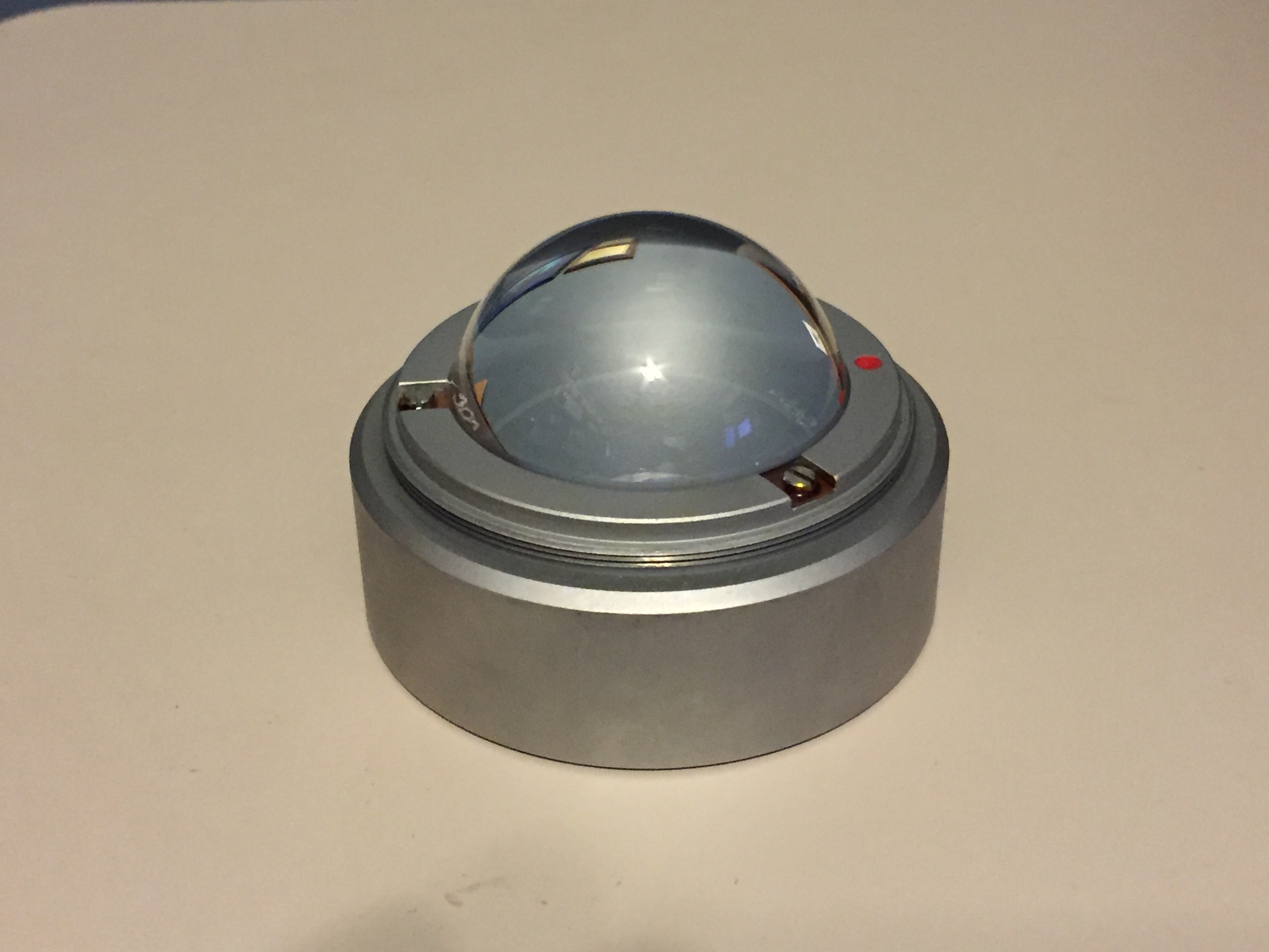
A precision sphere or hemisphere is sometimes included in the kit with a roundness measuring system. This is typically used for testing the instrument’s spindle. The sphere/hemisphere is very round. By measuring this very round sphere/hemisphere, your measurement results are primarily made up the instruments errors. Thus if you have a vibration you will see it in this measurement.
Here’s where things can go wrong. This ball is made to be “zero reference” (as if it can be considered to be perfect in comparison to the measuring instrument) but there is still some error in the ball. The actual errors in the ball are provided as a “certificate of calibration” for the ball.
The calibration lab typically arrives at the ball’s certified value by using extremely accurate methods and it often includes the use of a “reversal” which is something for another blog topic.
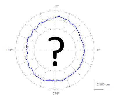
Here’s an example measurement on a precision hemisphere as analyze by OmniRound:
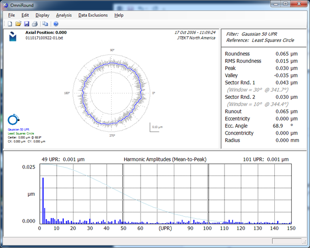
This hemisphere had a calibrated value of approximately 0.040 µm. The screen shows a roundness of 0.065 µm (when using a 50 UPR Gaussian filter). This means that the errors in the roundness instrument combine with the errors in the hemisphere to give a result of 0.065 µm. A more advanced “reversal” can be used to separate the instrument from the ball, but this requires two measurements, some very precise fixturing and software that performs the correction.
Can I “calibrate” with the ball? (The short answer is: no, no, no, no, no!)
In some cases, people have used the certified value for the sphere/hemisphere as the nominal value for a “calibration” of their roundness system. This is VERY dangerous! Remember that the word “calibrate” typically means “adjust” in a roundness system. Thus, in this example, if we “calibrated” the instrument with the hemisphere we will introduce a scale factor that will reduce the 0.065 µm value down to the certified 0.040 µm value. In this example, the factor would be 0.6; meaning all measured values would be reduced to only 0.6 of their actual value. A part that has a 10 micron roundness would only measure 6 microns!
Using a precision sphere/hemisphere to “calibrate/adjust” a roundness measuring system would be the same as using an optical flat to set the gain on an electronic indicator. There isn’t enough deflection to set the gain. Spheres/hemispheres and optical flats are “zero references” not gain adjusting tools.
Verifying and adjusting the probe gain
The probe sensitivity or “gain” is a factor that must be set and controlled in the roundness measuring system. For example, if a long stylus shaft is used there is a lower sensitivity. This sensitivity is represented by a “gain” value inside the instrument that must be set via a process that the system typically calls “calibration”. (Technically it’s an “adjustment” since we are changing things.)
To adjust the probe’s gain we need to exercise more of the probe’s motion. This is typically handled via a “Flick Standard” (also called a “Dynamic Standard”) or by gage blocks. Both of these approaches allow for checking the probe gain and/or adjusting the probe gain. Both have their pro’s and con’s.
The Flick/Dynamic Standard
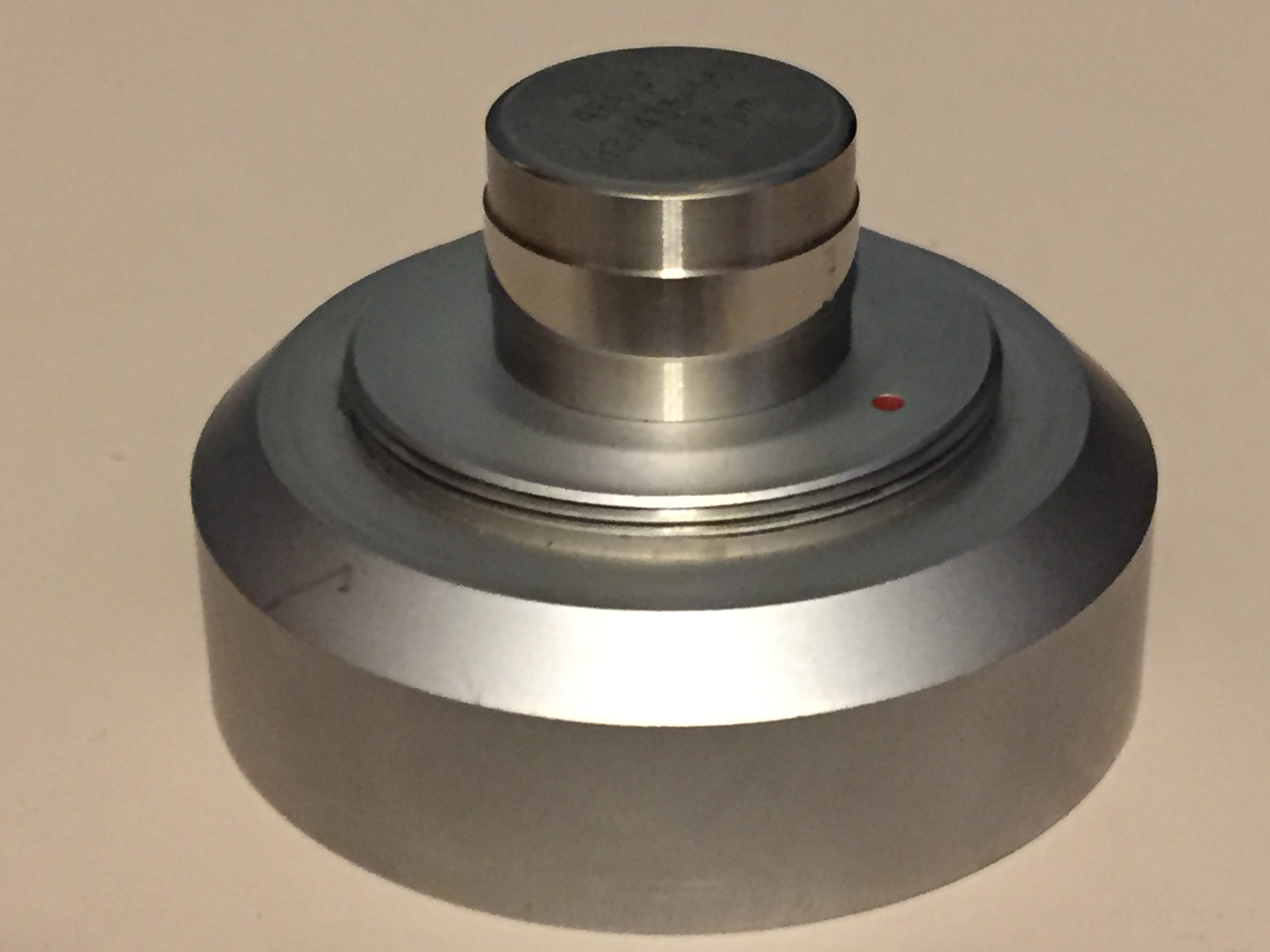
The “flick” or “dynamic” specimen is typically the easiest and can also be used for a quick check to see if the measuring system is giving back the expected roundness values. The specimen has a region that is very, very round with a “flat” ground into it. The roundness value is based on the depth of the flat area.
These specimens are typically more expensive and they must be properly calibrated. Furthermore, the measuring instrument needs to process the data in the same manner that the specimen was calibrated.
The calibration (I know I’m using the word to mean “adjustment”) process with a flick specimen involves.
- Center the flick standard – taking care to avoid the flick area while centering
- Measure the standard
- Scale the measured value to match the certified value via the instrument’s software.
Gage Blocks
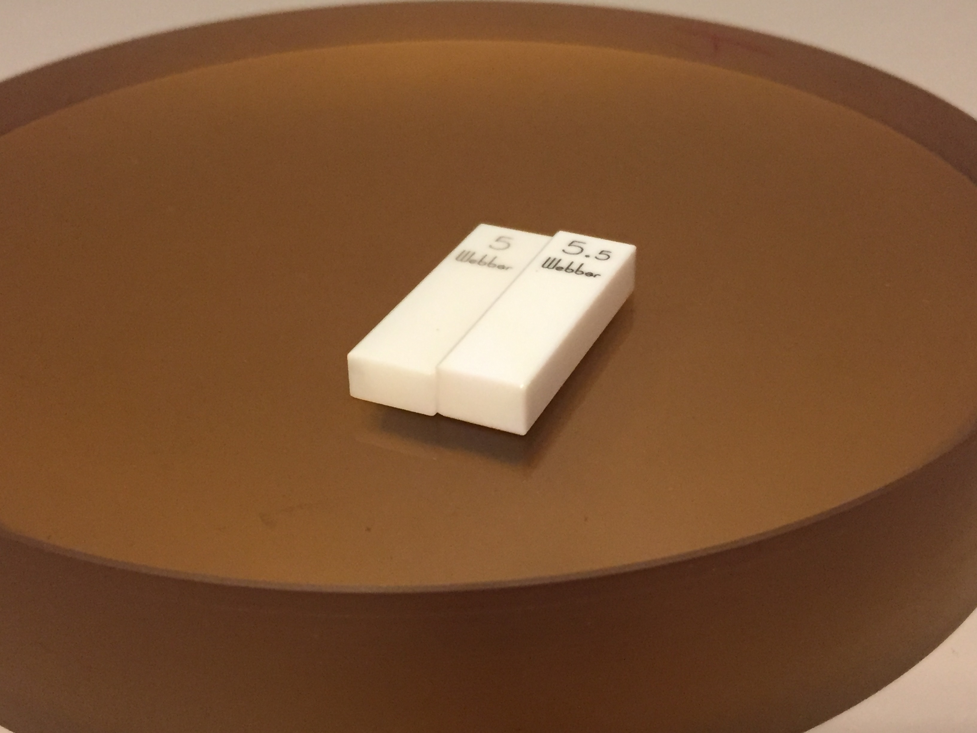
The gage block (gauge block, slip gauge, Jo-block) approach involves wringing two, certified gage blocks to an optical flat. The step height between the two blocks is used to test or set the probe’s gain.
The calibration (you’re right… I’m using that word to mean “adjustment”) process with a gage blocks involves.
- Level the optical flat
- Place the measuring stylus on one block and record the height
- Place the measuring stylus on the other block and record the height difference
- Scale the measured height difference to match height difference.
Wait a minute… gage blocks steps aren’t “roundness”!
Shouldn’t I use a radial (roundness-type) measurement to “calibrate” roundness not a vertical (gage-block) measurement? Not necessarily. The gain-setting operation should isolate the probe/stylus combination and move it through a known displacement. The orientation doesn’t necessarily matter other than it should be in a stable configuration.
How often should I do this?
The roundness measuring system should be checked and potentially “adjusted” whenever:
A new stylus or probe is inserted.
Different probe lengths and insertions lead to different sensitivities.
A new stylus contact angle is used.
Changing the contact angle changes the effective probe length.
There is doubt about the condition.
Did anything happen while I wasn’t looking?
The most efficient way of checking the probe gain is via a “flick” or “dynamic” calibration standard. Simply measure the standard and see if an adjustment is needed.
So there you have it…
Hopefully this will take some of the confusion out of the tools for roundness calibration. Digital Metrology always welcomes your questions and comments. Feel free to contact us today!