Many Coordinate Measuring Machine (CMM) providers are beginning to incorporate surface roughness measurement into their CMMs. Digital Metrology has had the privilege of collaborating on many of these projects. However, one question often arises:
Can we also measure waviness on a CMM?
Before we go too deep, we need to first be clear on the type of measuring system that is being used on the CMM: skidded or skidless.
A skidded system has a large radius in contact with the surface which provides a reference and keeps the diamond stylus in range during measurement. The skid slides along the surface during the measurement. The advantage is that a skidded system can be moved via the CMM over any measuring length. The disadvantage is that skidded probes can be used to measure roughness, but not waviness.
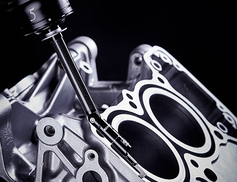
Photo courtesy of Renishaw.
Skidless system, on the other hand, can measure both roughness and waviness. However, in order to overcome CMM inaccuracies, noise and vibration these CMM-based skidless systems typically incorporate an independent traverse unit that is mounted on the CMM head. This independent unit accurately moves the stylus tip while it is held in place by the CMM. The disadvantage is that the traverse lengths are limited by the relatively small roughness traverse unit.
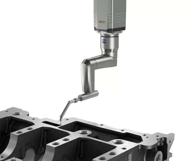
Photo courtesy of Zeiss.
But what about “waviness”?
Often a waviness analysis requires a longer evaluation length. Thus, it would be ideal to use the CMM itself for a waviness analysis – much like a typical straightness measurement. Can it be done?
That depends on two things: 1. Is my CMM accurate enough, and 2. Can a CMM stylus (ball) actually detect waviness?
The CMM accuracy must first be addressed. For example, if the CMM’s straightness errors for the desired measurement are a major percentage of your waviness (Wt) tolerance, then the CMM is probably not the best choice. The CMM’s ability to measure waviness can be determined by measuring the straightness (Wt) on an optical flat at the desired position over the desired length.
Can a CMM stylus ball actually measure waviness?
ISO 12780-2:201 indicates that, for a typical 0.8 mm waviness cutoff, a 0.5 mm tip radius (1.0 mm diameter) is acceptable. However, many users are skeptical about this and some companies even have internal standards saying that waviness must be measured with a roughness (diamond stylus) system.
Much of this confusion or misinterpretation of waviness comes from the aspect ratio of the profile graphs. Typical profile graphs are scaled with micrometers vs millimeters. This gives the impression that profile features are very narrow and steep… which is not actually the case.
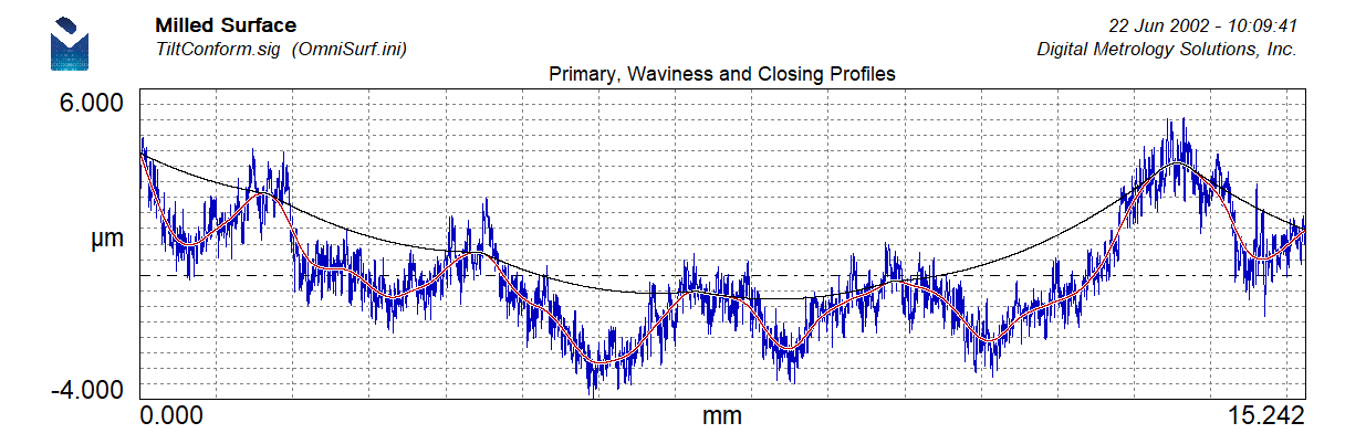
Let’s use Digital Metrology’s OmniSurf software to take a look at a typical surface that would be a candidate for CMM-based waviness. This is a surface from a milled engine block head deck – a component much like the one used in both pictures above.
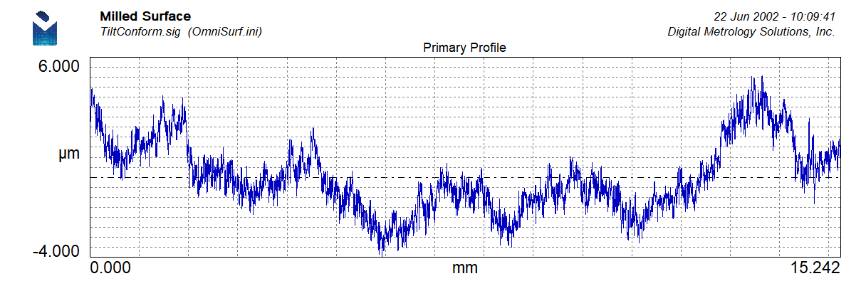
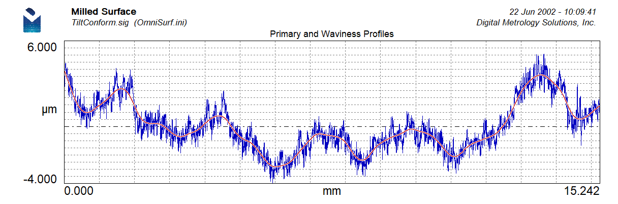
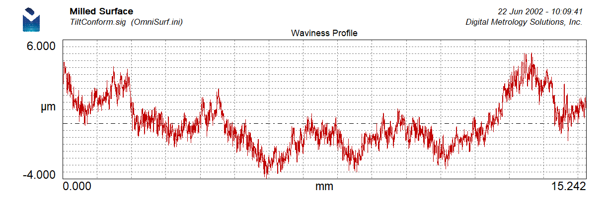
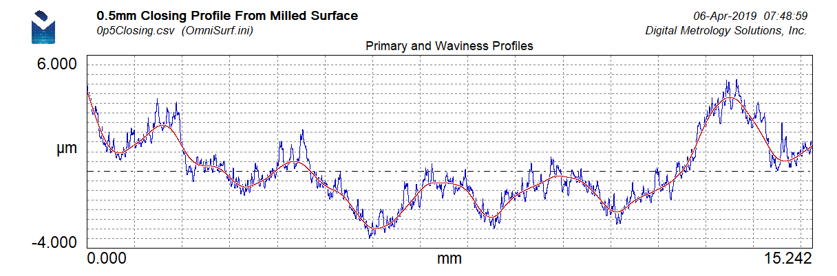
The above trace came from a traditional, skidless, diamond stylus-based surface texture measurement. We can see all of the roughness details as well as the underlying waviness. The waviness can be shown in OmniSurf simultaneously with the primary profile as follows. (Note: a 0.8 mm cutoff is shown.) This would be considered a “traditional” waviness profile.
In order to see how a CMM ball follows this surface we will use OmniSurf’s morphological closing filter. The closing filter acts like a virtual gasket by rolling a mathematical ball over the waviness profile.
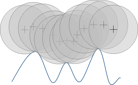
OmniSurf activates the closing filter when any of the virtual gasket parameters are selected (Wvoid, Wvdd). This is a useful analysis for predicting leakage under a gasket. For example, a 2000 mm radius can be used on the above data set to show the potential leak areas.
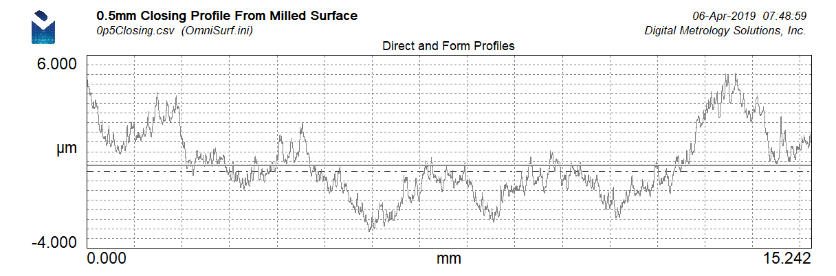
We can also use the closing filter to simulate the penetration of the CMM ball. To do so, we must keep in mind that OmniSurf applies the morphological filter to the waviness profile. Thus, we will set the roughness cutoff to a very small value (0.0025) in order to create a waviness profile that simulates the actual surface being measured.
We can now apply a closing filter based on the stylus tip radius. Let’s start with a 10 mm diameter (5 mm radius) ball:
The black curve above shows that the 5 mm diameter follows the general trends of the surface and actually sees a great deal of fine detail. So now let’s go to the 0.5 mm radius (1.0 mm diameter) and we see the following black profile as the stylus path:

The 0.5 mm tip radius reproduces a significant amount of the milled surface’s details! We will now export this (black) closing profile and bring it back into OmniSurf as a new profile.
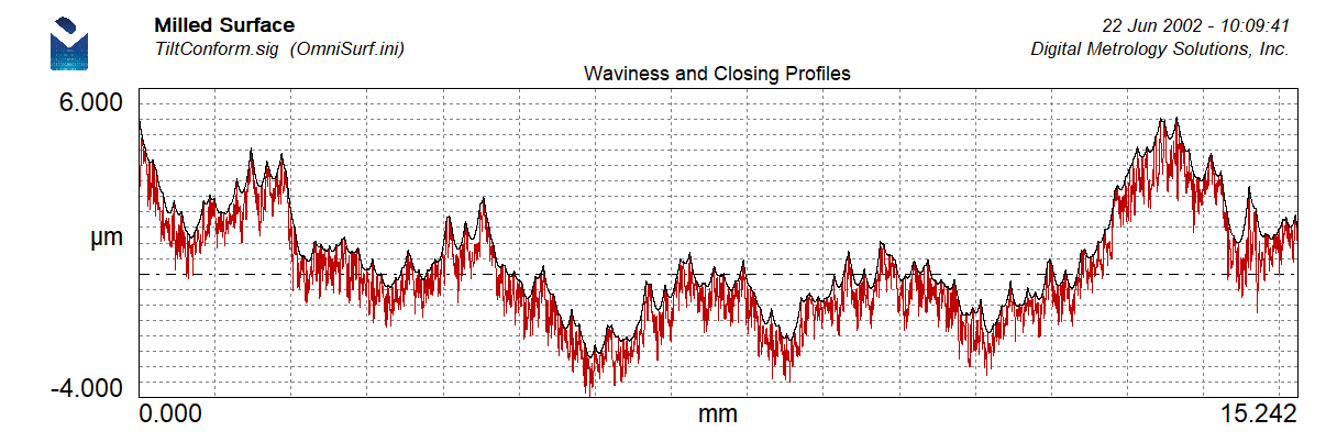
We can now filter this profile with the 0.8 mm waviness cutoff:
A side-by-side comparison shows amazingly similar waviness profiles:
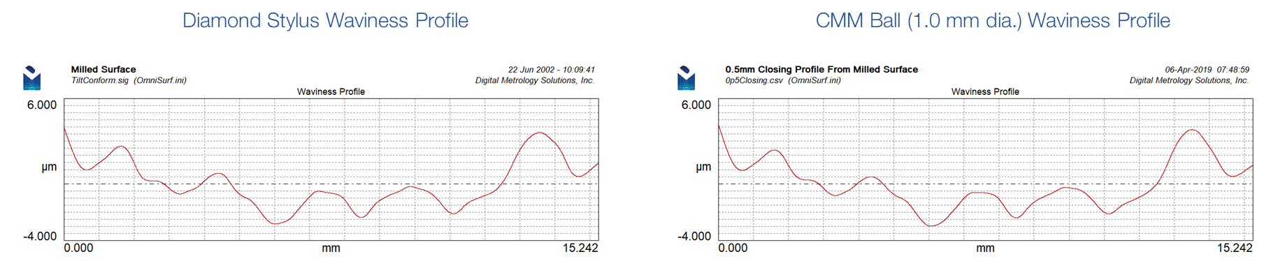
As this OmniSurf-based analysis shows, the resulting waviness profiles are very similar – indicating that it is indeed possible to measure waviness on a CMM.
It should be noted that this analysis is dependent on the surface having relatively uniform roughness. In cases where there are sporadic peaks, the CMM ball may be more sensitive to these high points and potentially give higher waviness values. The waviness generated by the diamond stylus will generally remain in the center of the profile in cases of sporadic peaks – especially when using robust filtering.
For more information on this topic, OmniSurf or to further explore measurement options for your surfaces, contact Digital Metrology today.