Many mechanical interfaces depend on the control of “flatness”. But what do we really mean by “flatness”? This is a question that is being raised more and more as tolerances are getting smaller and smaller. So what do you do when presented with a simple flatness tolerance and a surface to measure?
Let’s start with the definition. In the US, we have the standard ASME Y14.5 “Dimensioning and Tolerancing.” At the time of this blog post, the 2018 edition has recently been released. In it we see:
3.37 Flatness
Flatness is the condition of a surface or derived median plane having all elements in one plane.
But if we are going to measure flatness, we need to understand this definition a bit more. Specifically, “what’s an element?” Unfortunately, the work “element” is a generic term used throughout Y14.5 to imply anything of interest. For example, “elements” could be points, circular sections, linear sections, etc.
In the case of flatness, it makes the most sense from the measurement perspective to consider elements as the data points representing the surface. Thus, the metrology interpretation of 3.37 would be something like “flatness is the condition of a surface whereby all of the points are in one plane”.
But here’s the big question… ok there are actually two (related) questions?
How many points does it take? (Sampling)
And…
What kind of filtering/processing do we do with the points? (Smoothing)
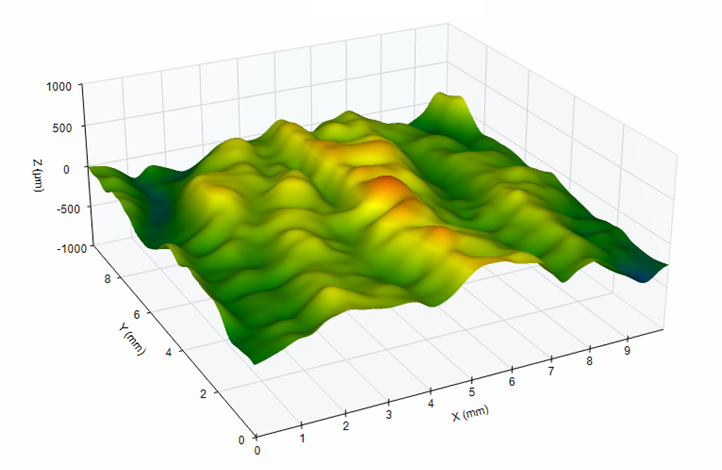
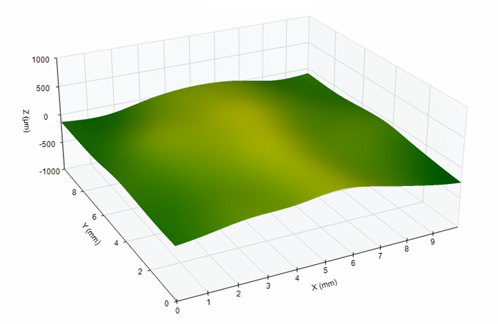
The fundamental challenge with understanding “flatness” boils down to “what do you really mean by flatness?” For example, this surface can have two, very different flatness values depending on sampling and smoothing:
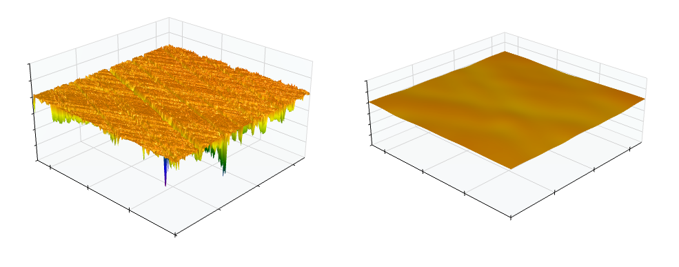
The reported flatness value depends on the surface wavelengths of interest. For the above surface, the unfiltered flatness (left) is many times greater than the smoothed flatness (right). The data on the left side includes all wavelengths. The data on the right side is smoothed to include only the longer wavelengths.
Does Y14.5 tell us anything about data points and smoothing?
Yes and no.
Rule #1 (section 5.8.1) famously states that perfect form is required at the maximum material condition. From the measurement perspective this implies the control of “all unfiltered data points”. Rule #1 is also referenced in the Y14.5 section 8.2 regarding “form control”.
Y14.5-2018 is the first revision to provide further clarification on the topic of data points and smoothing. A new “fundamental rule has been introduced in section 4.2 (note “s”) which states:
Unless otherwise specified (UOS), elements of a surface include surface texture and flaws (e.g., burrs and scratches). All elements of a surface shall be within the applicable specified tolerance zone boundaries.
This new note clarifies what was implied in previous versions of Y14.5; features of form are to include all aspects of surface geometry – regardess of the scale of the feature.
CONCLUSION from Y14.5-2018: Infinite number of data points. No smoothing.
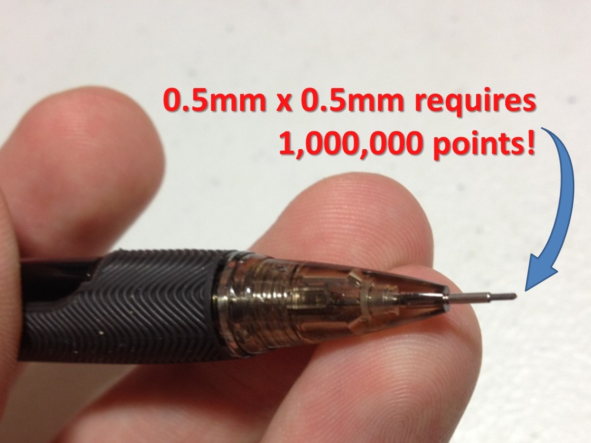
Practically speaking, we cannot measure all the way down to the last atom. Therefore, let’s limit our measurement of flatness to go down to the shortest limit of surface roughness. A typical roughness measurement is based on using a diamond stylus tip with a 2 micrometer radius (or smaller) and with a data point spacing of no more than 0.5 micrometers. This can result in an overwhelming number of data points as we consider flatness. A pencil tip of approximately 0.5mm by 0.5 mm puts this in perspective:
But there’s more to the story…
There is a bit of ambiguity in the US standards as we look a bit deeper. For example, ASME Y14.5 refers to ASME Y14.5.1-1994 for “Mathematical Definition of Dimensioning and Tolerancing Principles.” ASME Y14.5.1 has a section (2.1.1) on “Establishing the Surface Points.” This section indicates that there is certain amount of filtering needed to separate dimensional features from “micro” features like roughness. The context implies that “dimensional features” are those features defined in Y14.5… which includes flatness.
CONCLUSION from Y14.5.1-1994: Smooth out the roughness.
But wait! ASME Y14.5.1-1994 also refers to ASME B46.1. What does B46.1 say on this topic?
Along with the above mentioned note (2.1.1) ASME Y14.5.1 also gives reference to the use of “smoothing functions defined in ASME B46.1”
In the 1990’s ASME B46.1 (v1995 Section 1.2.2) included the concept of “error of Form” as being a type of shape. It described “errors of form” as being comprised of “widely spaced deviations which are not included in surface texture”. Since “surface texture” includes roughness and waviness, it implies that “form” is made up of wavelengths longer than waviness. This results in a “3 domain” definition:
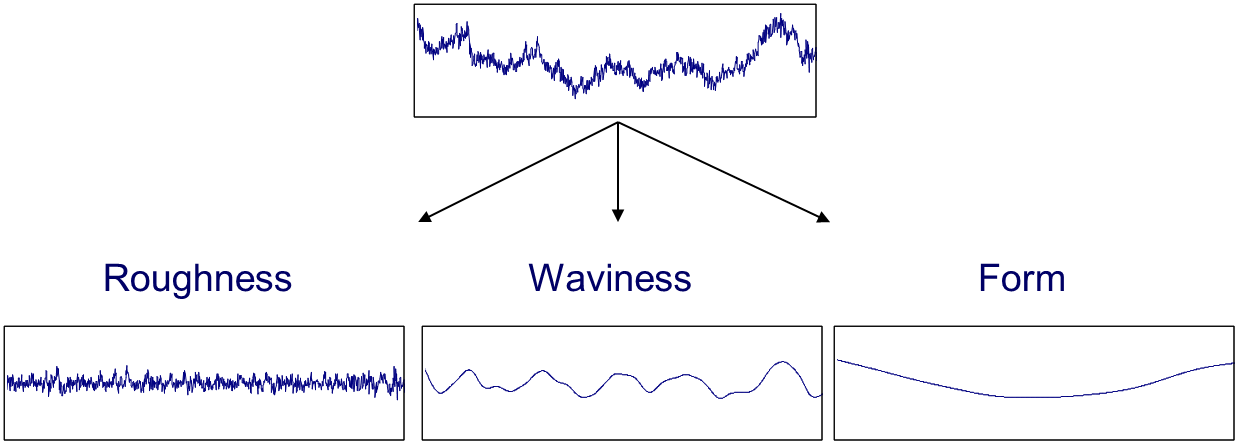
CONCLUSION from ASME B46.1-1995: Smooth out the roughness AND waviness for flatness.
So what is “flatness” in the United States?
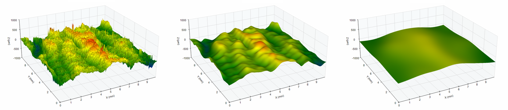
In the US we have 3 candidates for flatness per ASME standards: ASME Y14.5, ASME Y14.5.1, ASME B46.1 (pictured in order left to right)
What do International Standards say about flatness?
In its early drafts, ISO 12781-2 proposed the use of a 0.8 mm cutoff wavelength to remove short wavelengths (i.e. roughness) from flatness. This 0.8 mm value was chosen since it is the most common surface roughness cutoff wavelength. Thus, the idea was that there would be two domains: the roughness domain and the “form” domain.
This approach, whereby roughness is removed from flatness, is much more manageable than trying to use an infinite number of points with no filtering. However, it can still be difficult to achieve on very large surfaces. To transmit wavelengths longer than 0.8 mm, a 0.5 mm tip radius is required and the data point spacing must be no greater than 0.15 mm. Based on the implications of using this on large surfaces, this proposal was rejected by International balloting and the 0.8 mm filter cutoff was removed. A statement was added to the Standard’s introduction indicating:
At the current state of development, ISO TC 213 has not been able to reach a consensus on defaults for filter UPR, probe tip radius and method of association (reference plane). This means that a flatness specification must explicitly state which values are to be used for these specification operations in order for it to be unique.
CONCLUSION from ISO 12781-2 Early drafts: Smooth out the roughness.
It is important to note that all of the ISO discussions involved the smoothing out of roughness. The dissention regarding the 0.8 mm filter came from those that were dealing with large surfaces and they actually required more smoothing to extract their shapes of interest. This ultimately led to the note in the introduction to 12781-2 (2011).
CONCLUSION from ISO 12781-2 (2011): You must specify filtering, sampling, etc.
So… what should you do about this?
First off you need to determine what you mean by flatness. Are you interested in the general trends of the surface as flatness with aspects being controlled by waviness and/or roughness? Do you need all unfiltered points captured?
Ultimately the ISO 12781-2 (2011) standard gives us the best possible direction. In section 4.1 it tells us that the proper (unambiguous) specification of flatness “defines the transmission band”. Thus, if you want to control flatness – you need to indicate a wavelength band that describes what you mean by “flatness”. When presented with a flatness tolerance and a surface to measure, you must ask for more information. The tolerance limit alone is ambigous.
Still unsure?
For more information and for help specifying and measuring flatness and other surface-related challenges, contact Digital Metrology today!