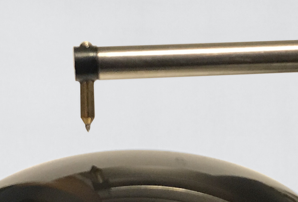
Many critical surfaces (ball bearings, bearing races, sockets and lenses, to name a few) are comprised of arcs or arc-like geometries. As with other critical surfaces, controlling roughness and waviness on these curved surfaces can be extremely important. However, measuring arcs on these surfaces with many traditional stylus-based instruments poses fundamental challenges.
In this post we look at several considerations that may be affecting your ability to properly measure arcs and understand your curved surfaces using a stylus instrument.
Errors due to surface “lay”
First off, we need to understand that when using a profile-based measurement we should measure across the surface lay–not along the lay. This can be a consideration when measuring over the arc of a shaft. In the case of a shaft produced by a manufacturing processes such as turning or grinding, the measurement should not be made in the circumferential direction. Circumferential profile measurements can be misleading. In some cases, where the stylus dwells on a ridge line or valley line, the roughness can be hidden. More commonly, the stylus may cross one or two ridge lines and distort the spacing between them. This can also result in reduced roughness as the feedrate features will appear as waviness.
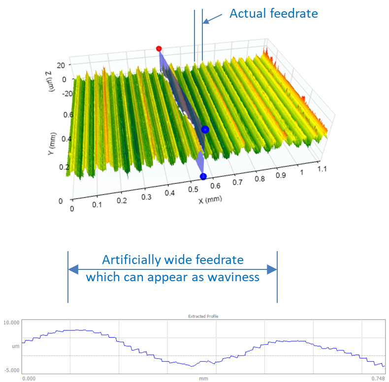
What can we do about the surface lay problem?
We should either measure axially (perpendicular to the lay) or use an areal/3D measurement.
Errors due to resolution
In many cases, the measuring range of a typical stylus instrument needs to be increased in order to collect an adequate length of data on an arc.
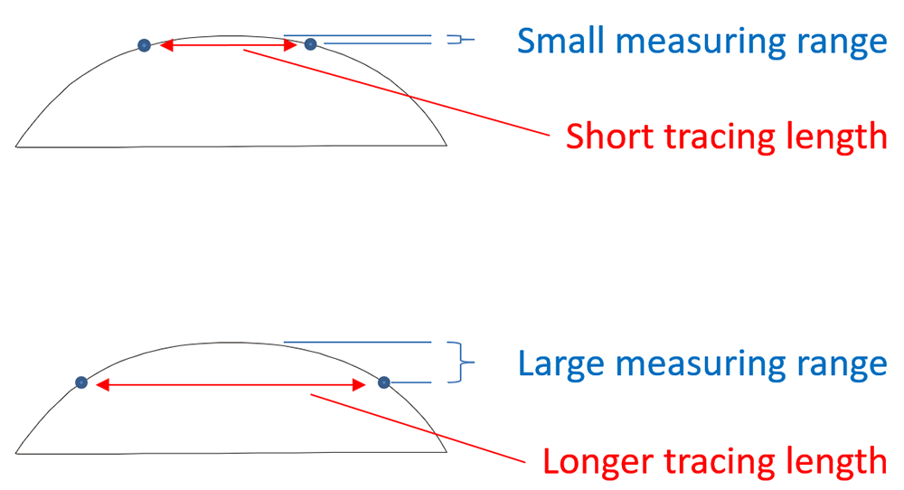
Increasing the measuring range can, however, hurt the instrument’s resolution. A typical roughness instrument has a limited number of vertical resolution “steps” within the selected vertical range. If the vertical range is increased, the step sizes must also increase. 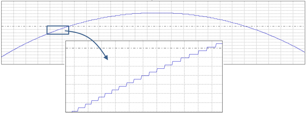
When the data is subsequently levelled and filtered, these “resolution steps” can show up as what appears to be “roughness:”

When using a large measuring range, some instruments not only measure with a lower resolution but they also perform their calculations at a lower resolution, which can result in a roughness profile with “digital steps.”

What can we do about the resolution problem?
There are basically two answers: 1) use an instrument with a larger range-to-resolution, or 2) sample the surface with multiple, short traces measured at a smaller vertical range. (Note: the short traces may not be able to detect waviness.)
Errors due to arcuate motion
The stylus of a profiling instrument does not move vertically. In fact, it moves along an arc. In other words, the stylus travel as based on “arcuate motion” whereby the tip moves along the horizontal (X) axis as a function of its vertical (Z) position.
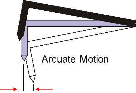
Given this motion, a typical stylus instrument can distort a perfect radius. Let’s consider a convex shape. As the stylus moves from left to right over the convex surface the stylus shifts to the left as it climbs. (Consider the white stylus above, moving to the gray, then to the black as it climbs.) This has the tendency of lagging behind and taking longer to climb up the radius. Similarly, as the stylus falls down the right side of a convex shape, it moves from black to gray to white (above), again resulting in distortion in the measurement.

The arcuate motion results in a distorted measurement profile of this form:

A similar error occurs when measuring a concave surface:

The motion results in a distorted measurement profile of this form:

One way to determine if arcuate error is affecting your results is to make a measurement. Rotate the measured component 180°. If the shape remains constant (for example, the right side is always steep), then the instrument is causing the error. If the shape moves with the component, then the shape is likely attributable to the component geometry.
What can we do about arcuate errors?
The only way that arcuate error can be addressed is to use an instrument that calibrates and corrects for the arcuate motion of the stylus. Most common roughness instruments set a gain value with a roughness patch. These instruments cannot correct for arcuate motion. Instruments that can correct for arcuate motion are calibrated with precision spheres/hemispheres or precision angles/prisms.
Errors due to filtering a curve
When measuring a curved profile it is important to remove the curvature before filtering for roughness and waviness. Some instruments do not have the ability to suppress advanced geometries such as arcs or polynomials, and this can result in a shift in the roughness profile when using a traditional Gaussian filter.
Some background… in order to assess “roughness” we need to first remove “waviness.” This is performed by a filter (see our post, “3 Steps to Understanding Surface Texture”). This filter is typically a Gaussian-weighted moving average. However, if we pass a moving average over a curved surface, the moving average will be biased “downward” for a convex surface and “upward” for a concave surface.
We can see this effect by taking an average of a region of points on an arc:

We determine waviness by moving the average over the length of the profile, which results in a waviness profile (red) that sits below the primary profile (blue) as shown here. 
Here is a real-world example of this effect: the calculated waviness profile (red) clearly sits below the primary profile (blue).

Since the roughness profile is based on subtracting the waviness profile from the primary profile, we will end up with a roughness profile that sits above the zero line (for a convex surface). This upward shift can have significant impact on roughness parameters.
We can demonstrate this effect in our OmniSurf software on an actual, measured dataset. A convex profile was analyzed without first removing the arc, and a standard Gaussian filter was applied. This resulted in an “upwardly shifted” roughness profile and an average roughness (Ra) value of 0.254 micrometers.

However, if we suppress an arc prior to filtering with the Gaussian, the filter does not shift the profile and we get a more realistic roughness value. In fact this roughness value is MUCH smaller than that which resulted from the shifted profile.

What can we do about the meanline shift?
The best option is to remove the nominal geometry prior to filtering. If your measuring instrument does not have this option, then Digital Metrology’s OmniSurf can handle it for you. Another option is to use a 2nd order filter. These filters are being discussed in ISO standards and are not yet generally available in most measuring systems.
Wrapping thing up…
As you can see, a seemingly simple measurement can sometimes be very misleading, and bad decisions can be made based on these error sources. In cases like this, Digital Metrology can step in and help you manage and understand your measurements. Better yet, Digital Metrology can help you understand your surfaces and what makes them work.
For more information on the measurement of arcs and many other surfaces and shapes, contact Digital Metrology today!
