“Why would you use that antique measuring system? Today we have optics!”
If you use a stylus based system (aka a “profilometer” or a “roughness gage”) to measure surface texture you may have heard some version of that statement over the years. Measuring with a stylus can seem low tech or even old fashioned…but in fact, both stylus and optical technologies have their place, and which one is “best” depends entirely on the application.
What are the technologies?
Let’s do a quick recap of the technologies we’re discussing.
Stylus profilometry has been in use since the early 1900’s. In a stylus instrument, a “sharp” stylus is moved across a surface. The stylus tip traces a line along the surface. Along the way, the vertical positions are recorded to produce a “profile” that represents the surface.
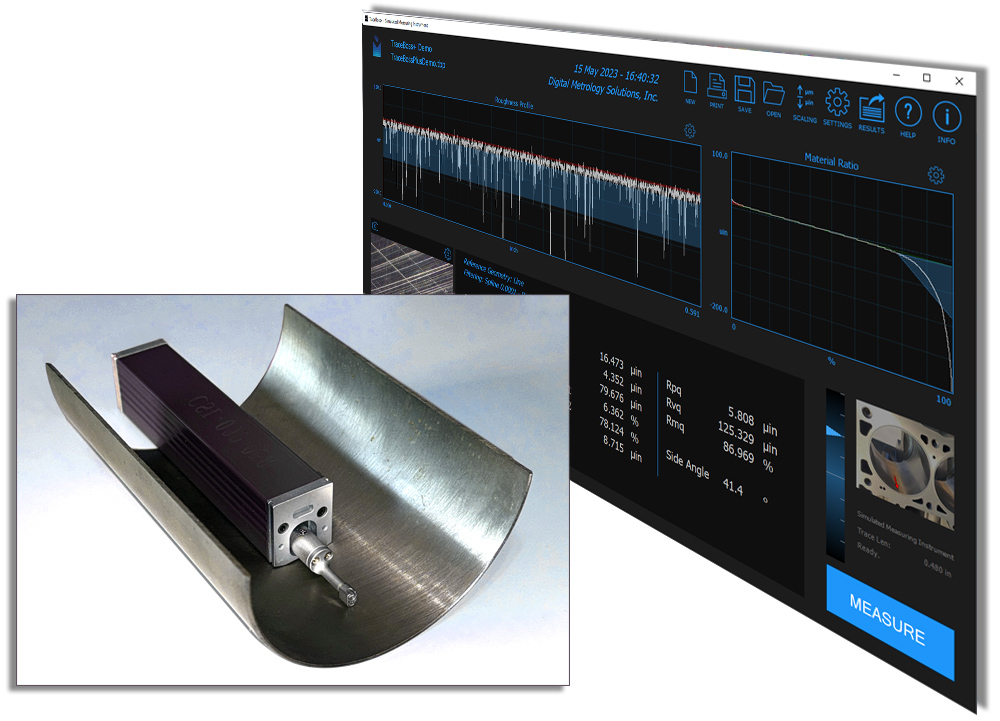
A stylus profilometer on a surface, and a 2D profile in TraceBoss+ software.
Stylus gages are typically of two forms. “Skidded” instruments include a large skid which rides on the surface while the stylus moves relative to the skid. These systems are typically lower cost and can only be used for roughness measurements. They are often more robust and better suited for difficult environments. The other type of stylus instruments is “skidless.” Skidless instruments record the stylus deflections relative to a precision reference or “datum,” so they can measure longer wavelength waviness in addition to roughness.
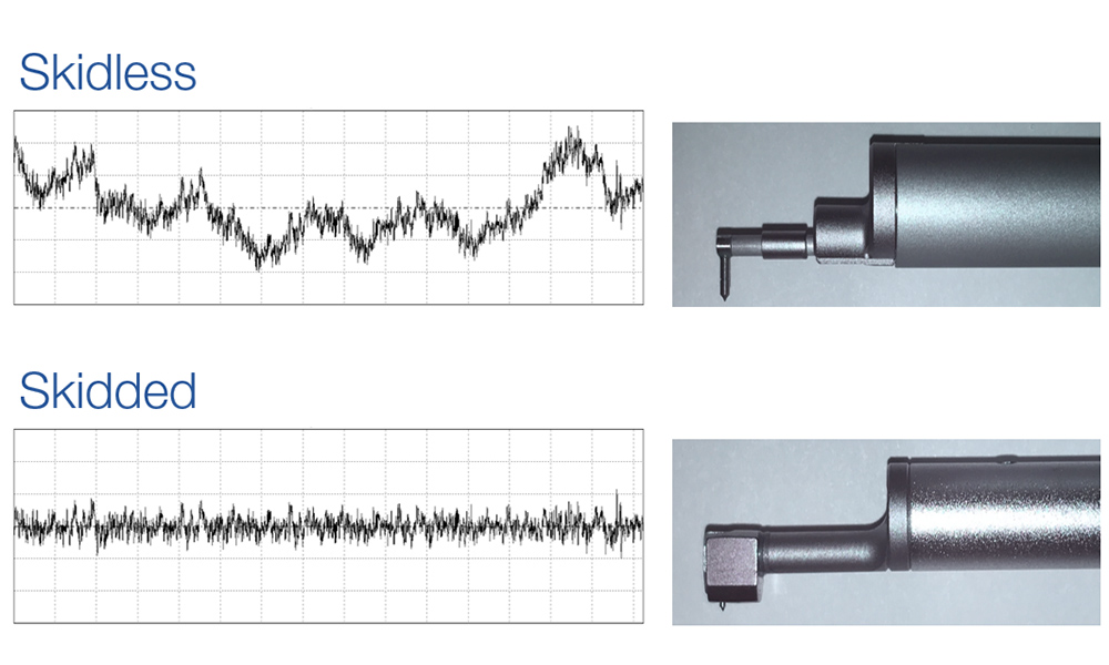
A skidless stylus for larger vertical range measurements, and a skidded stylus for roughness measurement (courtesy The Surface Texture Answer Book).
Non-contact, 3D optical metrology techniques started becoming popular in the late 1980s. These systems exploit properties of light and optics to measure surface heights, typically over an area, rather than along a single profile. Many optical techniques are now available, with some of the popular methods including coherence scanning interferometry, phase-shifting interferometry, confocal microscopy, and focus variation microscopy. Each has unique advantages that make them valuable for industry and research.
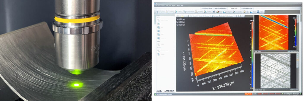
3D optical profiler objective and 3D surface data.
So how do these technologies compare? Let’s look at a few key points.
2D vs 3D data
One of the advantages of optical measurement techniques is they produce 3D data maps, which can help us see and understand what’s happening on a surface much more readily than we can with a single profile (or a single parameter value for that matter!). This “3D” ability revolutionized how we interact with surface texture.
An areal (3D) measurement may be more likely to capture surface features that could be missed altogether by a single stylus trace. The deepest or tallest portion of the feature (like a tiny pit or small nodule) is also more likely to be captured by an areal measurement. Thus, critical surface parameters may be measured more accurately with an areal measurement system.
Pits and pores can only be reliably measured via 3D/areal systems.
3D aspects of a surface, such as the volume of fluid that can be retained, can only be measured using 3D techniques. Finally, a profile measurement can’t tell us whether a low point is an individual “pit” or one point in a long “valley”—we need a 3D map to see that.
One aspect of 3D measurement that is not always obvious, however, is the overall size of an individual acquisition (i.e., one measurement). A 3D measurement can look like a vast landscape…but in reality, it may be quite small. The figure below shows typical low resolution and high resolution optical measurements as compared to a standard stylus profile. With typical 3D measurements, we get a lot of data points…but over a small area!
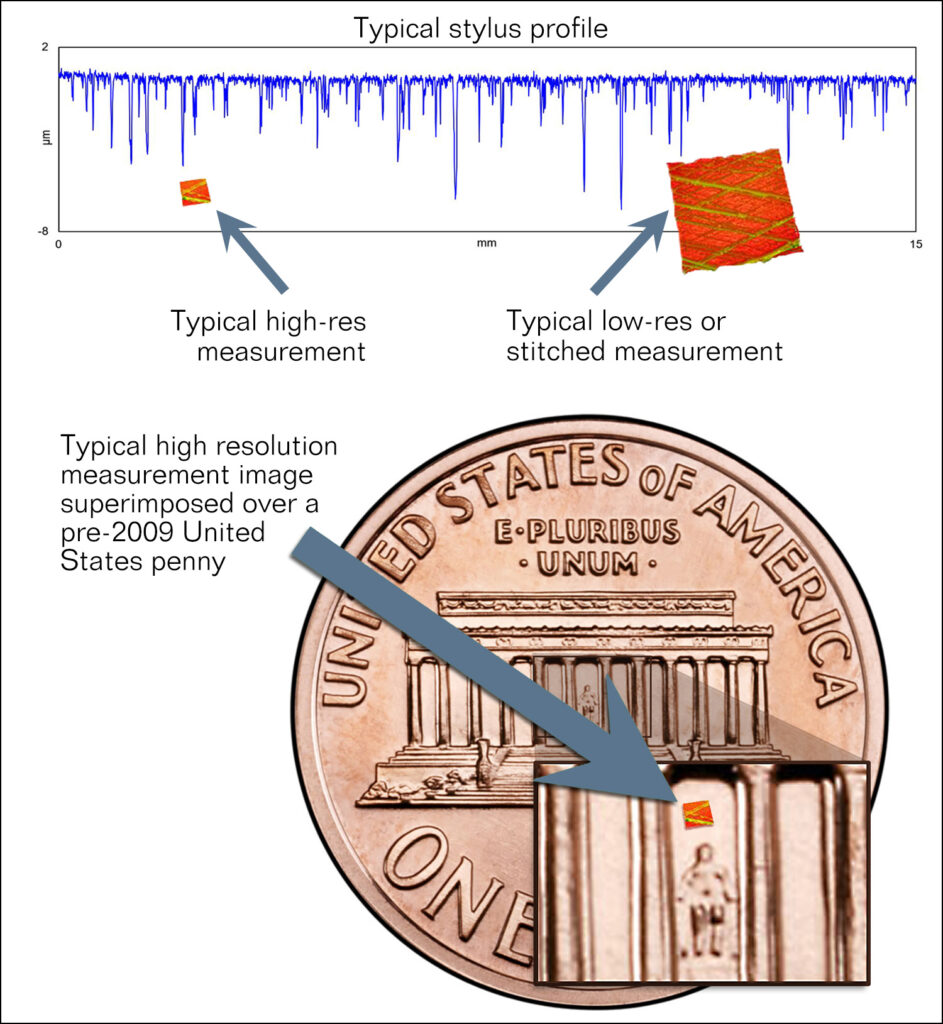
The millions of data points in an optical 3D profiler measurement constitute only a tiny measurement area. Image courtesy The Surface Texture Answer Book.
Speed
Some optical metrology systems can acquire measurement data very quickly. A phase-shifting measurement of a smooth surface, for example, may take a few seconds or less. However, roughness measurements on more typical machined surfaces can take considerably longer. To analyze grinding or honing, for example, a coherence scanning optical profiler may take 10–15 seconds for a measurement.
What’s more, those numbers are just from the acquisition time. If we look at the total measurement cycle time, optical may not be faster at all. An optical system can take time to align, locate features, and focus. Challenging geometries or materials may require additional adjustments. A handheld stylus instrument, on the other hand, can often simply be placed on the surface to be measured, typically with just a few settings to adjust.
Resolution and Accuracy
Optical systems may appear to win the resolution battle. We might think that “those millions of data points certainly seem like high resolution…and surely measuring with light must be able to capture smaller scales than moving a stylus over a surface”. However, there is much more to this topic. Let’s take a deeper dive.
The geometry of a stylus does in fact limit the smallest sizes that we can measure. In this chart the surface’s wavelengths are shown along the x-axis, with the smallest wavelengths to the left. The y-axis shows the transmission at each wavelength (that is, the degree to which the instrument can actually detect and measure each wavelength). At the left of the chart, we see that 0% of those very short wavelengths are transmitted (or “can be measured”) by the stylus. At the right of the chart, 100% of the height of the longer wavelengths can be measured.
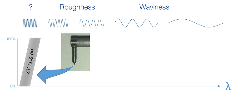
The smallest wavelengths that a stylus can measure is limited by the tip geometry.
A stylus cannot detect or record the features that are smaller than its tip radius. At slightly longer wavelengths, the instrument can sense the wavelengths to some extent, but these numbers are not reliable. At even longer wavelengths, the instrument can accurately detect and report 100% of the height of those wavelengths.
Can an optical system do better? Possibly…but an optical system also has limitations. For example, the diffraction limit of the optical system, the numerical aperture, the pixel size in the sensor, etc., can all play a role in limiting the measurable wavelength range. As with the stylus, there is still a range of wavelength scales where an optical system’s results are not 100% reliable.
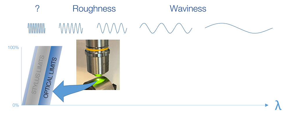
The smallest wavelengths that an optical system can measure is limited by the properties of the optical system.
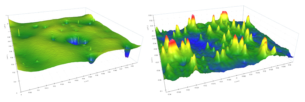
Furthermore, the simple selection of a different lens/objective can completely change the range of measurable wavelengths. It’s very common to find that people choose a lower magnification in order to see a larger measurement area (field of view), which results in lower lateral resolution or “wavelength transmission.” These two data sets where measured in the same area on a sandpaper surface. The left image was acquired with a higher magnification lens. We can see that the finer details (shorter wavelengths) are lost in the image on the right (acquired with a lower magnification lens).
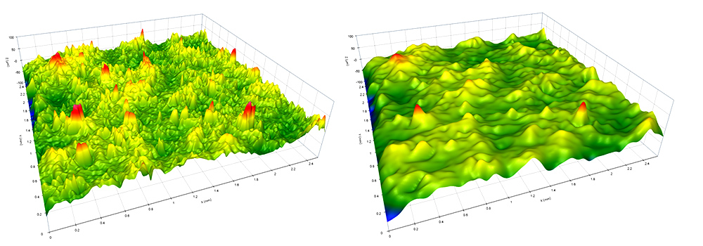
Comparison of an 80x objective and a 20x objective (Keyence VR 3100) on the same sandpaper surface.
If we want to correlate measurements between the technologies, we can apply a short filter at a wavelength long enough to ensure 100% transmission in both measurements. The short filter ensures that indeterminate, short-wavelength data is excluded from our results.
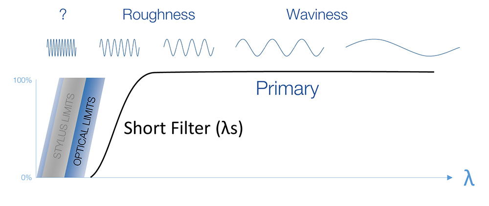
A short filter excludes the shortest wavelengths where results are unreliable.
Waviness measurement
In applications where waviness matters, we typically need a longer length (or larger area) of data. A stylus can acquire a long trace (often tens of millimeters) and can assess both roughness and waviness simultaneously—typically in less than a minute. On an optical system, measurements at “roughness resolution” are typically small, so we need to “stitch” together many measurements to acquire waviness data similar to that of the stylus. This stitching requires a much longer measurement process.
A stylus instrument has a long, internal datum bar that we trace along for skidless measurements. The small errors in that datum can be mapped and corrected so that long stylus traces remain highly accurate.
3D optical measurements also have a high-quality reference, but when we stitch individual, small measurements errors can be introduced. During the stitching process the software must rely on small zones of overlap between the acquisitions to estimate the relative tilt and position between the patches. Any instability in those small regions can lead to errors that may be propagated across the measurement, either amplifying the curvature, or flattening it out (as in the example below), hiding what could be an important error in the surface.
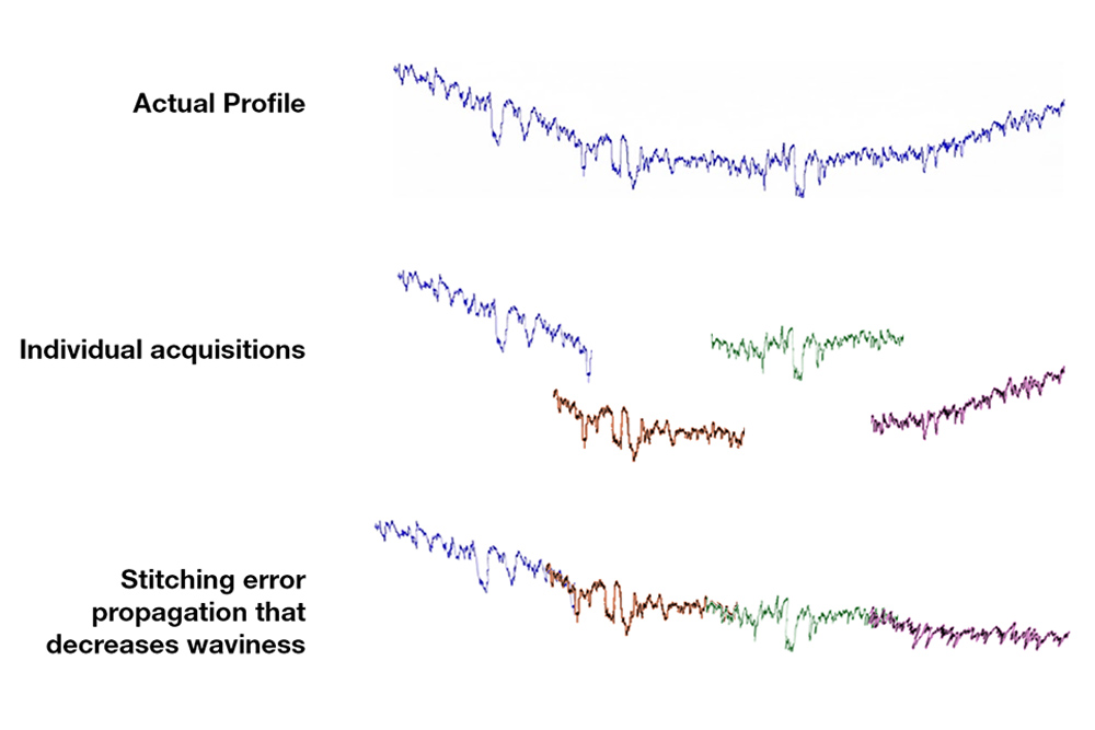
In a stitched, optical measurement, instability in the overlapping stitched regions can lead to inaccurate measurement of long wavelength waviness.
Production measurement
Measurements in manufacturing environments are often influenced by vibration. Many optical systems are highly susceptible to vibration, so these instruments must typically be well isolated by vibration dampening systems. These instruments also typically require physical separation from machinery, traffic, and air handlers. For these reasons, typical optical instruments tend to be far removed from the processes where they are most needed, tucked away in a metrology lab or cleanroom space.
While a skidless stylus measurement may also be influenced by vibration, a skidded stylus can measure roughness in much less ideal environments. This ability to measure despite a degree of vibration makes it possible to measure (at least roughness) right at the point where process control is required, rather than placing parts into a queue for an instrument in an isolated lab.
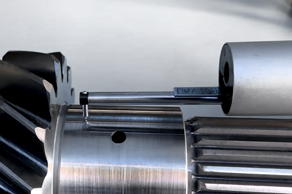
A skidless stylus measuring a production shaft journal.
Measurable materials
Some materials may be challenging to measure on an optical system, depending on the instrument’s sensing method. For example, highly reflective optics or surfaces with steep slopes can scatter light, causing the measurement system to “miss” the information at these pixels. The measurement will be compromised if the surface cannot reflect sufficient light or texture back to the measurement optics. A stylus instrument may be a better solution some cases.
Another consideration is the hardness of the material being measured. A stylus may scratch softer materials such as plastics or optical coatings, making a non-contact optical method more appropriate.
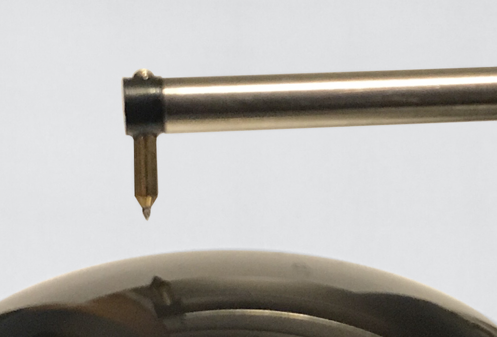
A skidless stylus measuring a spherical surface.
Measurable features
Both stylus-based and optical systems have advantages for particular kinds of features and geometries. An optical system can discern a pit from a valley, for example, as we mentioned earlier. An optical system may be able to measure in a small O-ring groove or a tiny annular ring that may challenging with a stylus. Mirror attachments can enable optical measurement inside of small bores that are inaccessible with a stylus.
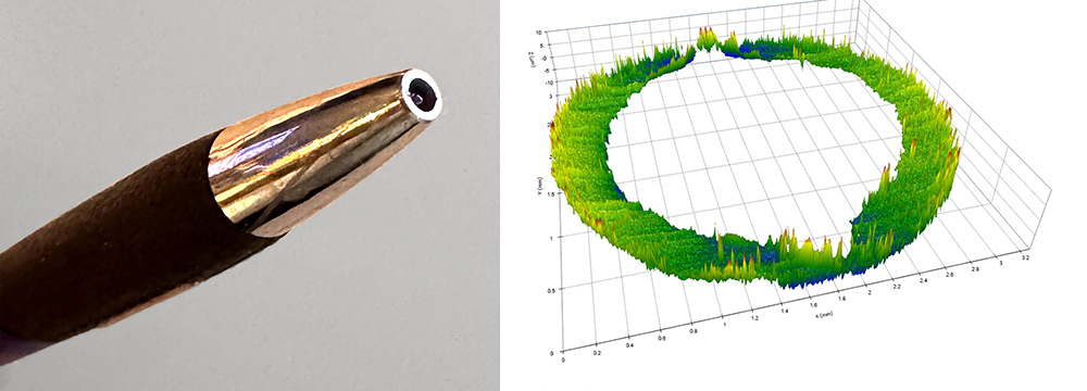
Measurement of surface texture on the tip of a ball point pen body. This would be difficult with a stylus.
Learning curve
The learning curve is often overlooked, but it can vary significantly across measurement systems. It’s an important consideration when purchasing a system, but also an ongoing consideration when re-deploying an existing system or when teaching new users.
In a production setting, both stylus and optical instruments can be programmed to measure with a single mouse click. But when the application requires a user to know how to configure the system, a stylus typically has fewer options and considerations. Stylus instruments (especially lower cost, handheld profilometers) are relatively easy to learn to use. A new user can pick up the basics in a few minutes.
While some optical systems are simple to learn, most involve many more settings and considerations, all of which can make the difference between good and bad data.
Cost
When cost is the primary factor for choosing a measurement system, stylus profilometers are typically the hands-down winner. A handheld skidded stylus can often be purchased for under $3000—even less on the used market. While entry level optical systems have come down dramatically in price in recent years, most optical instruments will cost significantly more than a stylus and will require additional infrastructure as well.
To be fair…
Hopefully the takeaway from all this discussion is that both stylus and optical measurement instruments have their applications. The instrument of choice should be based on the measurement needs: surface material, feature geometry, speed and resolution, cost, and ease of use. The goal is to get the right data—not necessarily to use the coolest new tools.