For many industries, waviness is a critical aspect of surface texture. The presence of waviness on a surface can be directly connected to functional problems such as noise, vibration, excessive wear and sealing issues. So, if we are going to control waviness, we need to first understand that there are two different interpretations of waviness in use today.
Most frequently waviness is treated as “one-sided” – meaning that all long wavelengths are considered as waviness. However, in some industries it is important to treat waviness as a specific “band” of wavelengths.
Let’s explore both waviness approaches by analyzing this familiar surface.
NOTE: This example surface profile is included with Digital Metrology’s OmniSurf software. The file is named “TiltConform.sig” and can be found in the “Example Data” subfolder.
Traditional (one-sided) Waviness
In common practice (particularly in the Western world) our measuring systems tend to separate a surface profile into short (roughness) and long (waviness) wavelengths. If we were to apply this common roughness and waviness specification on a profile, we would see something like this on a drawing:

This specification means that short wavelengths (between 0.0025 and 0.8 millimeters) are classified as roughness and are controlled by the average roughness (“Ra”) parameter. Wavelengths longer than 0.8 millimeters are classified as waviness and are controlled by the total waviness (“Wt”) parameter. This specification will separate the above example data as follows:

In terms of wavelength transmission, we have these two domains:

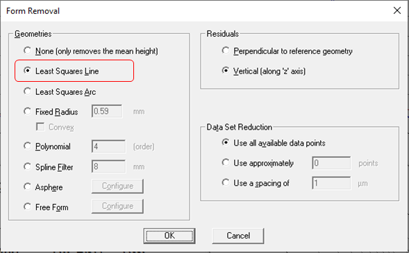
In OmniSurf we would set our form removal to be the nominal geometric shape of the surface (in this case a line). We do this by choosing Form Removal from the Analysis Menu:
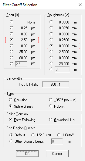
Our filtering (Analysis Menu > Filtering) would set the 0.0025 – 0.8 millimeter roughness domain:

Bandpass Waviness
Bandpass waviness allows us to separate surface texture into 3 domains: roughness, waviness and form. A specification of bandpass waviness may look like this:

This specification means that short wavelengths (between 0.0025 and 0.8 millimeters) are classified as roughness and are controlled by the average roughness (“Ra”) parameter. Wavelengths between 0.8 and 8.0 millimeters are classified as waviness and are controlled by the total waviness (“Wt”) parameter. Wavelengths longer than 8.0 millimeters are considered form and are controlled by the total form (“Ft”) parameter. This specification will separate the above example data as follows:

In terms of wavelength transmission, we have these three domains:

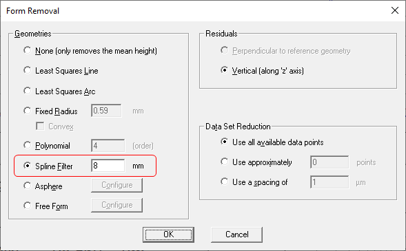
In OmniSurf we would set our form removal to be the 8.0 millimeter cutoff form filter (Analysis Menu > Form Removal). Note that when you use a filter for form removal, OmniSurf automatically includes levelling via a least squares line, and the form filter is a form-following spline filter.
Our filtering (Analysis Menu > Filtering) would set the 0.0025 – 0.8 millimeter roughness domain in the same manner as the one-sided waviness.

Wrapping things up…
Controlling waviness may be the key to solving your surface-related challenges. However, along the way you will need to decide if waviness should control all long waves or a band of waves. Here’s another way of visualizing the difference.
Traditional Waviness Separation

Bandpass Waviness Separation

For more help with getting a handle on your waviness problems, check out the OmniSurf software or contact Digital Metrology today!


