In many laboratories and production environments, we encounter surface texture calibration patches that look like this.
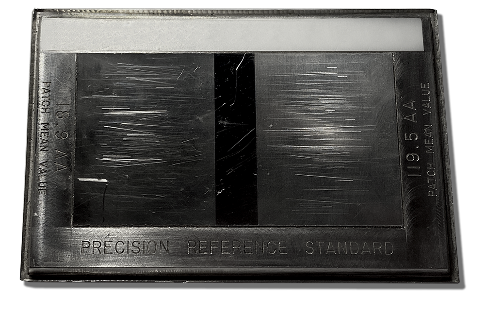
Hopefully yours don’t look quite this bad, but let’s take a deeper look at this damage.
Calibration patch surfaces are typically made of electroformed nickel, so they can be relatively soft. As a result, we often assume that the stylus is damaging the surface. After all, the stylus is very sharp, and diamonds are very hard.
But a 3D (areal) measurement can surprise you.
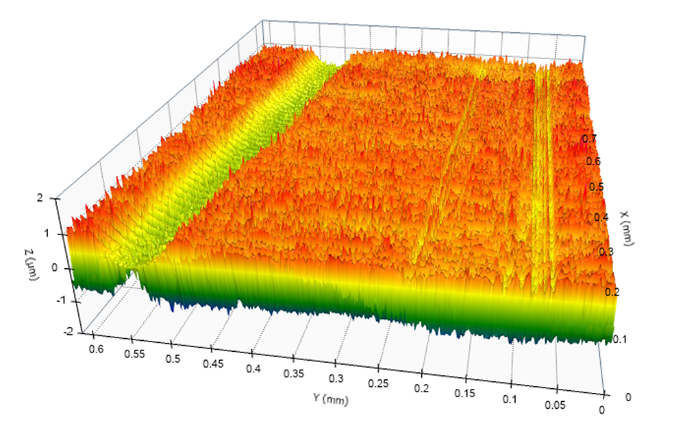
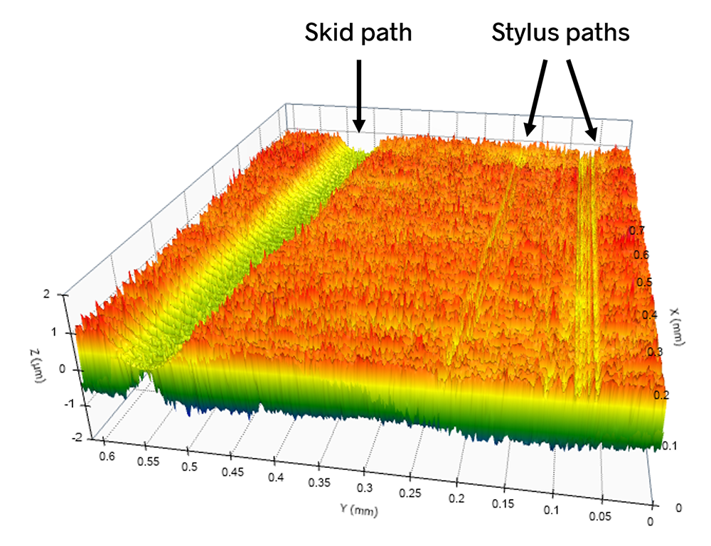
The above data set shows a wide path and several narrow paths. The wide path is actually due to excessive pressure on the skid of a skidded measuring instrument.
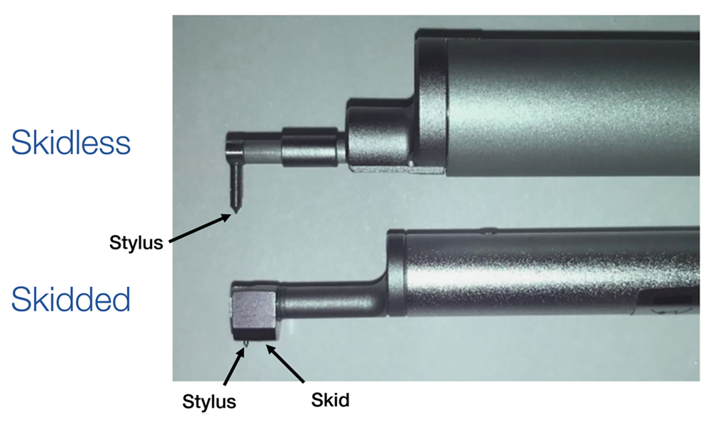
The damage can be caused by the skid
Stylus pressure is generally controlled by national and international standards as well as manufacturers’ recommendations. However, the skid pressure is not always controlled so tightly. In fact, many measurement systems have rather high skid forces to maintain solid contact and stability.
So what we really have on this surface is damage resulting from different measuring instruments.
What trouble can the damage cause?
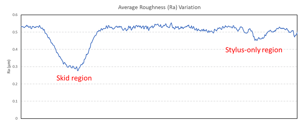
The ultimate purpose of the calibration specimen is to maintain consistent parameter values over the surface. We can study this variation via the profile extraction tool in OmniSurf3D. In this case, we will extract all profiles along the x-axis and batch process them via OmniSurf (2D).
When we do so, we can quickly see that the average roughness (Ra) value is significantly impacted in the region of the skid damage.
NOTE: This is not a measured profile, but rather a plot of the Ra roughness values as we work our way across the patch.
Using OmniSurf 2D and 3D to explore skid damage
To further explore the damage caused by a skid, a skidded instrument with a 3 mm skid radius (in the transverse direction) was configured with additional weight. The weighted skid produced this damage on the calibration patch:
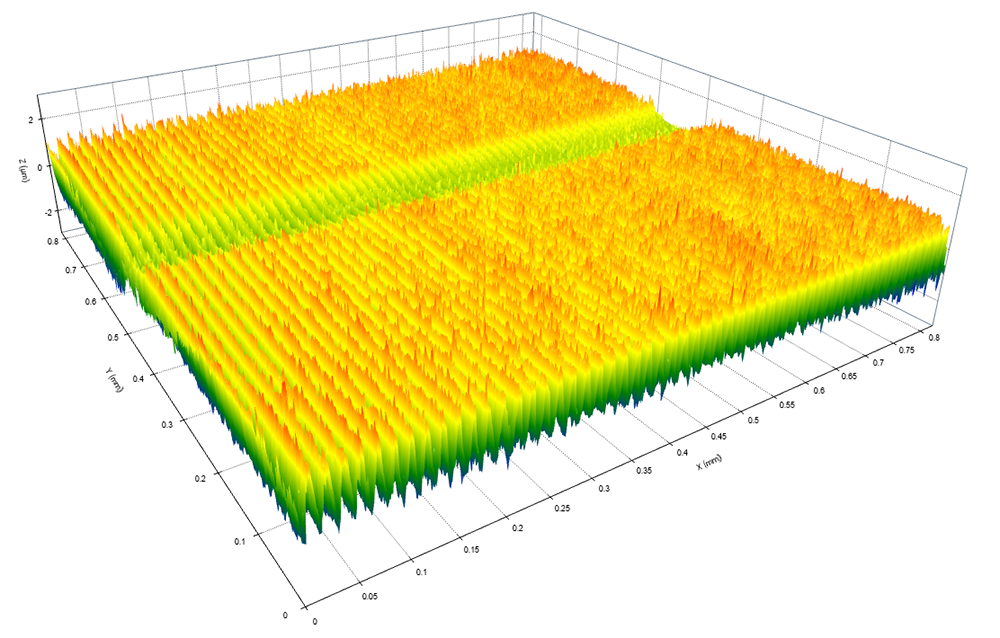
Using the OmniSurf3D profile sectioning tool, we can fine tune a cross-section along the surface ridges:
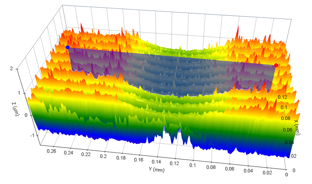
The profile can be sent directly to OmniSurf (2D) and we can apply this radius calculation on a selected region:

The OmniSurf (2D) radius calculation gives a 3.5 mm radius in the damaged region. This is close to the known 3 mm skid radius and tends to be very reasonable given the material deformation and relaxation in the wear zone.
So what have we learned?
First off, damage to the calibration patch may not be completely related to your stylus. Your skid may be doing the bulk of the damage. In fact, it can cause significant changes in the reported Ra values.
Secondly, OmniSurf3D working in conjunction with OmniSurf (2D) can provide a powerful set of tools for analyzing surfaces such as this one.
To learn more, contact Digital Metrology today.
