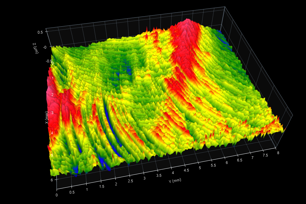
How can you tell where a crack will form? It’s particularly difficult for a surface such as this one, with complex texture consisting of machining marks from various operations. Perhaps we would look for the deepest scratches (the blue areas in the image above) to predict where cracking may occur. However, cracks tend to form at the sharpest concentrators, not necessarily at the deep departures.
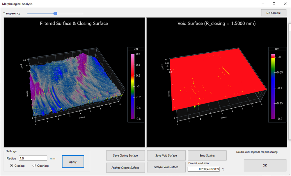
The Morphological Filter analysis in OmniSurf3D (Tools > Morphological Analysis) can uncover these sharp edges. Applying a “closing filter” to the data creates a “void surface,” based on the difference between a closing surface and the actual surface. The void surface can highlight leak paths or, in this case, area of sharp cracks/maximum stress.
Below, the left image shows the closing surface as a semi-transparent, blue layer on the original data. The right image shows the void areas that the closing filter doesn’t touch as valleys/pits. These void areas are likely crack initiation sites. These are the areas of greatest concern for cracking, despite all of the competing surface marks. Adjust the Radius of the filter to see how it affects the size and number of found features.

This dataset was featured in our article, Predicting Surface Functions with Morphological Analysis, in Aerospace Manufacturing and Design Magazine, July 2019.
Measured with Bruker NP Flex.
Data source: Michigan Metrology, LLC (www.michmet.com)
Please log in below to download the datasets. If you’re new to the page, please take a moment to register here.
I forgot my password
How to cite
If you use this dataset, please reference it as follows:
Digital Metrology Solutions. “Surface Library.” Digitalmetrology, digitalmetrology.com/dataset/crack-initiation. Accessed Mar 31, 2025.


