
Predicting fatigue failure: a better texture parameter
Additive manufacturing has grown increasingly popular, especially for producing critical components. With this growth we’ve also seen a resurgence of interest in surface texture, especially for understanding how it relates to fatigue failures such as cracking and breakage.
In the simplest terms, a crack that may lead to failure can occur at any sufficiently deep and “sharp” surface feature. In a lot of the literature on crack development, many researchers focus on valley depth, using roughness parameters such as Rv (the maximum depth along a 2D profile) and Sv (the maximum depth of a 3D surface area) to try to predict and prevent cracking. These parameters, however, have significant shortcomings.
A better way to predict cracking is to focus on the sharpness of features rather than the depth. In this tutorial we’ll show you better methods and parameters for estimating sharpness. To get there, however, we first have to consider where on on a surface cracks are most likely to form.
The valley problem
A lot of literature suggests that the deepest valley in a surface is the most likely feature to cause a failure.
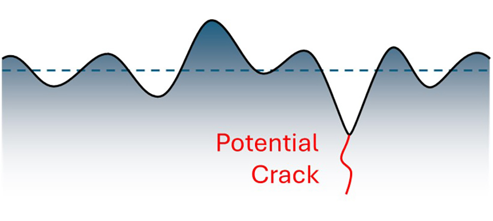
A crack propagating from the deepest valley.
The “valley depth” profile parameter (Rv) tells us this maximum depth, and therefore Rv is typically specified. Unfortunately, there are a few problems with the Rv parameter. To begin, there are multiple definitions of Rv, which can, of course, be a recipe for confusion:
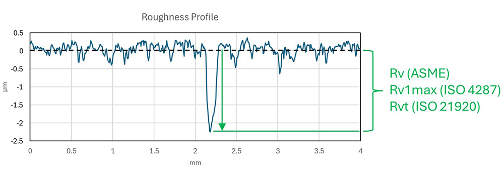
Parameters for depth of deepest valley.

Parameters for average valley depth.
By default, most stylus-based measuring systems use the ISO-defined Rv for profile analysis. But by this definition, Rv is an averaged value, not the single, deepest value, and this can lead to relatively small reported depths. Many researchers may not understand this aspect of the ISO-defined Rv, and the smaller values it reports can be very misleading.
On the other hand, in areal/3D surface texture analysis, the Sv parameter (ISO 25178) represents the single lowest point in the entire surface, more akin to the 2D ISO Rv1max parameter. It’s confusing! And, relying on a single data point (which could easily be noise or bad data) out of millions of points in a 3D dataset is not a good strategy for controlling a process.
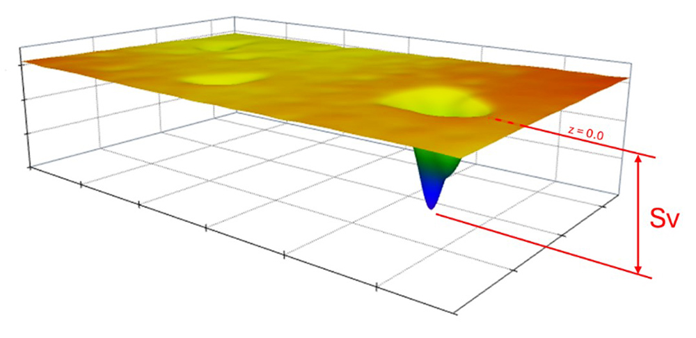
By ISO definition, Sv is based on the single, deepest valley/pit.
The differences in Rv definitions is one issue, but there is a more a fundamental problem: the deepest valley may not be the sharpest feature! A crack may propagate from a different, sharper valley, or, because of curvature, a crack may develop from a shallower valley.
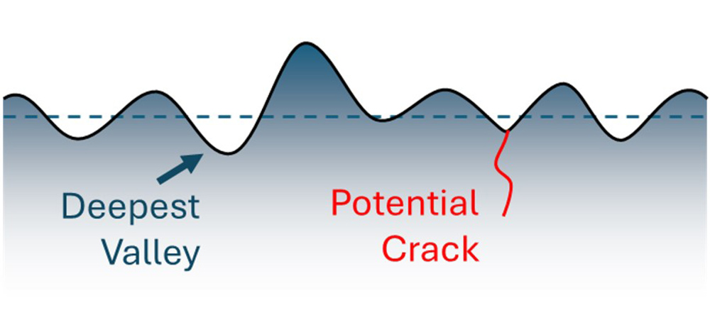
Due to curvature, a crack may appear above the deepest valley.
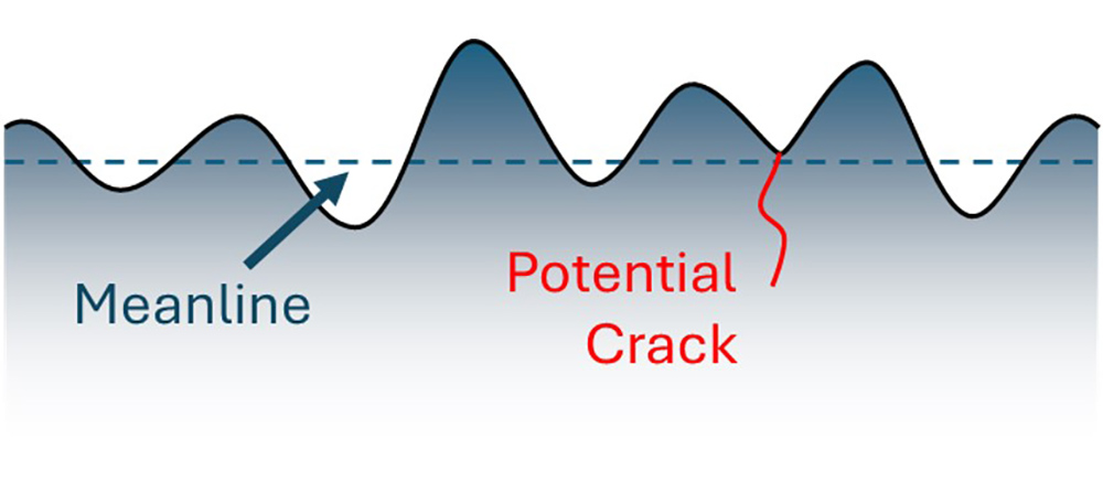
A crack may even form from a valley above the meanline (due, again, to curvature).
Focusing on valley “sharpness” rather than depth
Instead of focusing on depth, we can instead consider the “sharpness” of a valley as a better predictor of fatigue failure or cracking. A common way to stop a crack from propagating is to drill a hole at the end of the crack, because the hole increases the radius and reduces stress concentrations. Punching a hole in a chip bag has a similar effect.
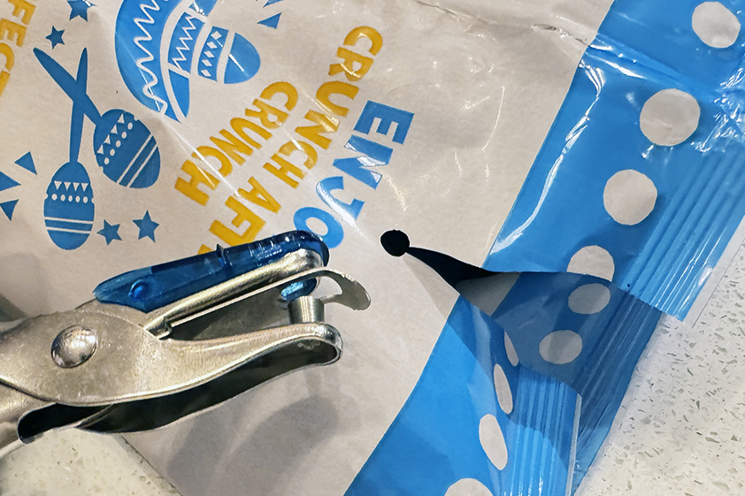
Punching a hole at the end of the tear in this bag increases the radius and can stop the tear from propagating.
So, knowing that valley sharpness may predict cracking, we may be inclined to look for a way to calculate the radius of each valley in the texture. In that way we might be able to locate and analyze the sharpest features. Unfortunately, valleys are typically irregular in shape, which makes it hard to reliably calculate a radius. In the example below, the radius of the entire valley is quite different than the radius calculated in one local area. The number of points we use to measure the valley (or more generally, the width of a region of interest) will also greatly impact the reported radius values.
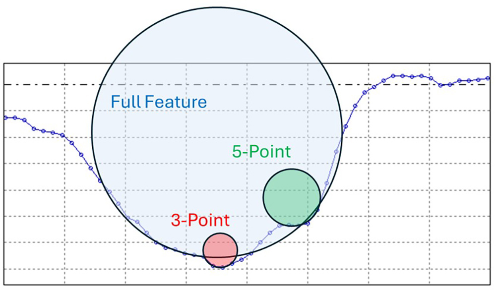
Question: what’s the radius of this valley? Answer: it depends…
Instead of attempting to calculate a radius for each features of interest, let’s take a different approach: let’s start by considering the smallest acceptable curvature, a radius beyond which a surface may be “sharp” enough to form a crack. We can then use that curvature as a limiting radius and measure surface features against it. This method is known as “morphological filtering,” and it is described in the ISO 16610-49 and ISO 16610-85 standards. We can apply a morphological “closing” filter to a profile by “rolling” a mathematical disk over the measured data points. The resulting path of the disk’s motion is called the “closing profile.”
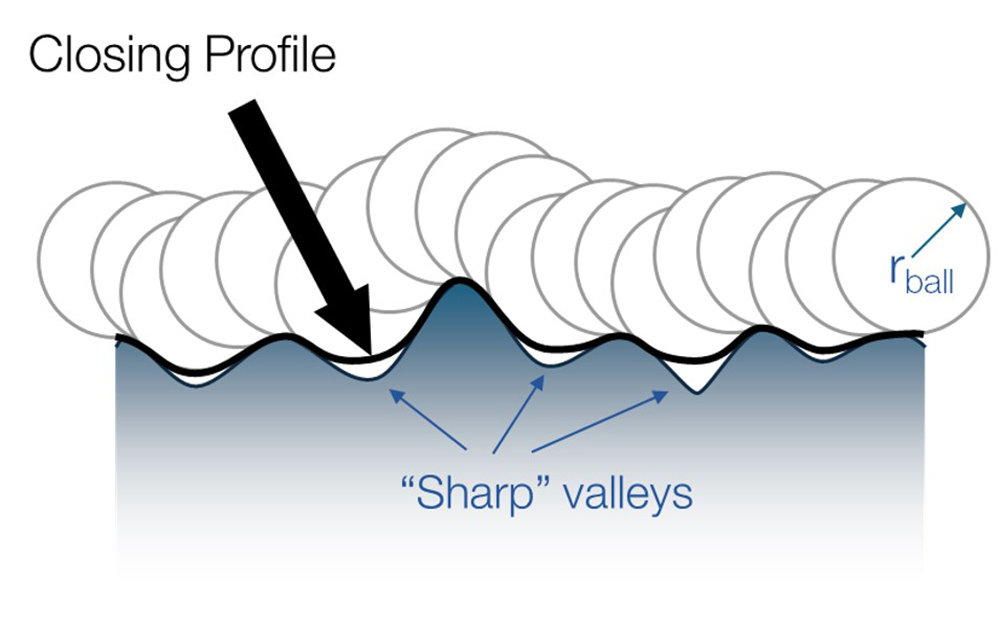
A morphological closing profile for radius r.
For areal/3D data, we roll a mathematical ball over the surface, creating a “closing surface.”
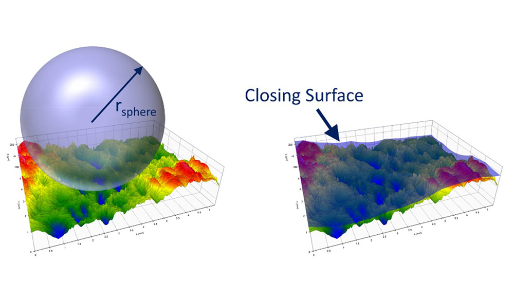
A closing surface for a given radius.
In the images above, the profile features that are “sharper” than the closing radius create gaps, or “voids,” under the closing profile. If we set the radius based on the curvature that we know leads to crack propagation, the voids represent the regions that could relate to cracking and fatigue.
Once we have the closing profile, we can calculate the deepest void or “maximum void depth.” Combining a void depth and a related closing radius, directly ties our notion of crack sensitivity back to “depth and sharpness.”
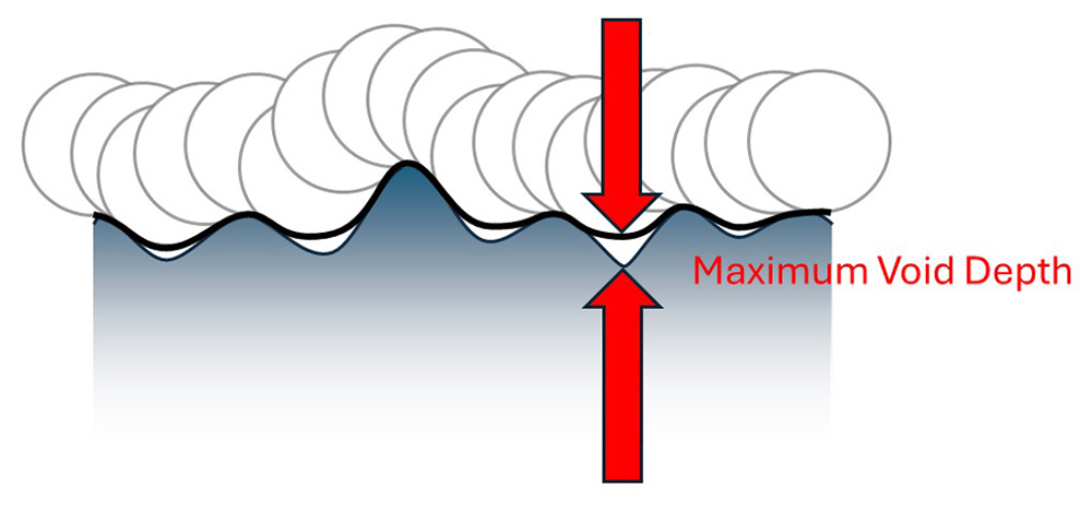
The maximum void depth (Wvdd, Svdd) is a good predictor of failure.
“Morphological void depth” analysis has been developed by Digital Metrology Solutions. Its reported as “Wvdd” for profile/2D analysis in OmniSurf software (operating on a waviness profile) or as “Svdd” for Areal/3D analysis in OmniSurf3D software. These parameters can be excellent predictors of cracking failure. Some measurement methods and filtering are required to use the analysis correctly, which we will discuss later in this tutorial.
Benefits of the closing filter approach
One of the principal benefits of this approach is that the void depth parameter is based on both the sharpness and the effective depth of features. Traditional texture parameters overestimate feature depths, as they treat the entire valley depth (relative to the meanline) as significant. From a material perspective this is not necessarily the case: the effective depth should be considered as the depth of the sharp region, not the entire valley. Furthermore, the position relative to the meanline is not as significant when it comes to stress-causing texture features. The morphological void approach does a better job reporting on likely failure-causing features from a materials-based perspective as well as pure geometry.
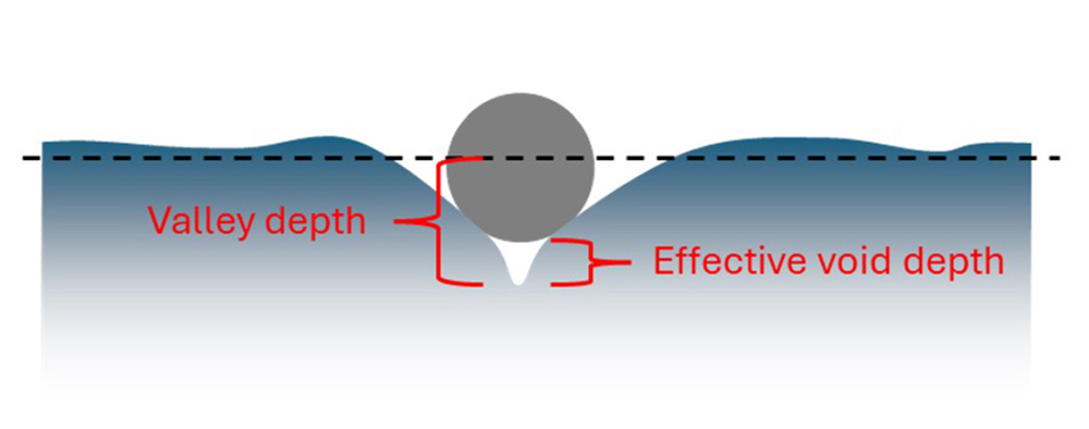
Unlike Rv (valley depth), the effective void depth considers just the “sharp” part of the valley where cracking is more likely.
Another significant advantage of analyzing morphological void depth is that the parameter is not related to the meanline or mean plane of the surface. Sharp features will be detected regardless of their vertical position, so the sharpest feature will be located, even if it is not the deepest valley, as in the examples below.
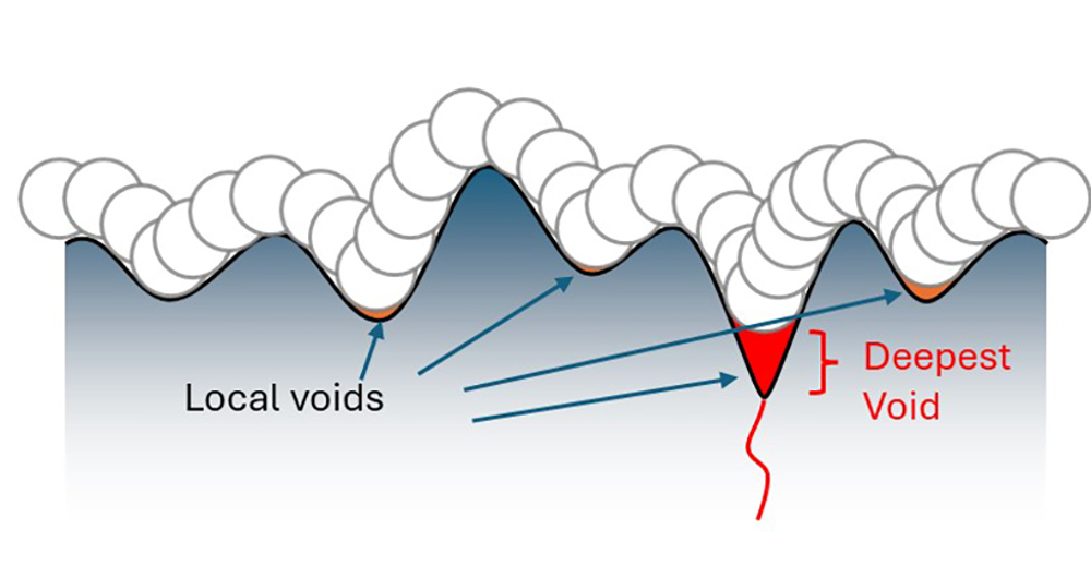
A profile where the “deepest sharp void” occurs in the deepest valley.
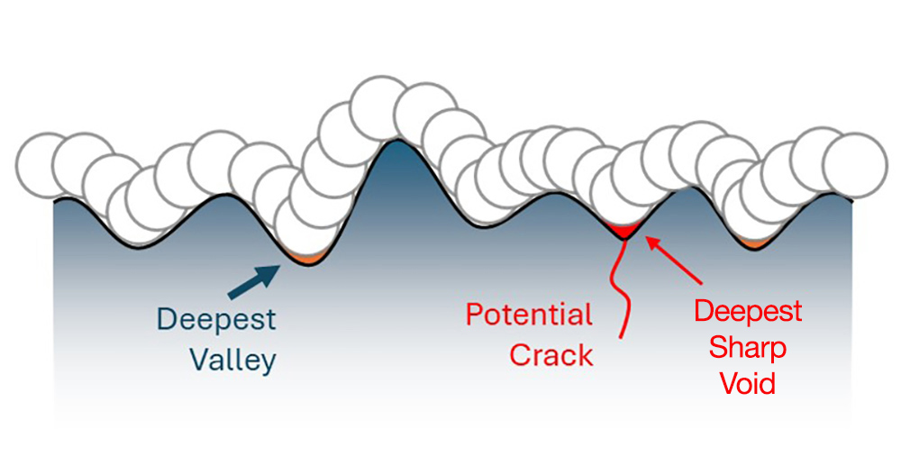
A profile where the “deepest sharp void” is not the deepest valley.
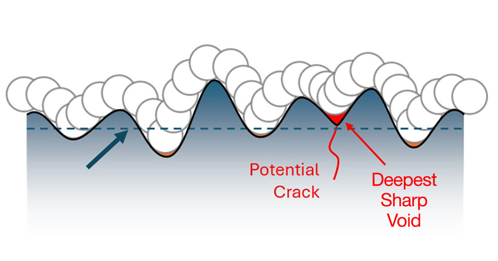
A profile where the “deepest sharp void” is above the meanline.
Measurement and analysis implications
Common, profile-based surface texture measurements use a diamond stylus, most often 2 µm in radius. The radius of the stylus tip acts as a mechanical filter, since the tip itself can not resolve smaller features. We can think of this in terms of the wavelengths that can be detected by the stylus. Short wavelengths are not transmitted, as indicated by 0% on this graph. Longer wavelengths can be fully (100%) transmitted.
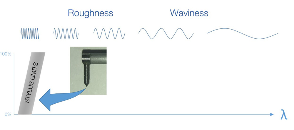
Wavelengths transmitted by a stylus instrument.
The smallest features that can be resolved by optical instruments with standard objectives and magnifications is also limited by the system optics. It would seem that a light-based system would have better lateral resolution than a mechanical probe—yet, many common optical instrument configurations have less lateral resolution than a stylus.
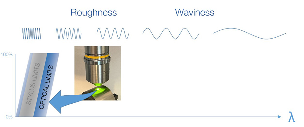
Wavelengths transmitted by optical instruments as compared to stylus instruments.
Ideally, we want to use an instrument for which the measurable wavelengths overlap with the scales of interest for our surfaces.
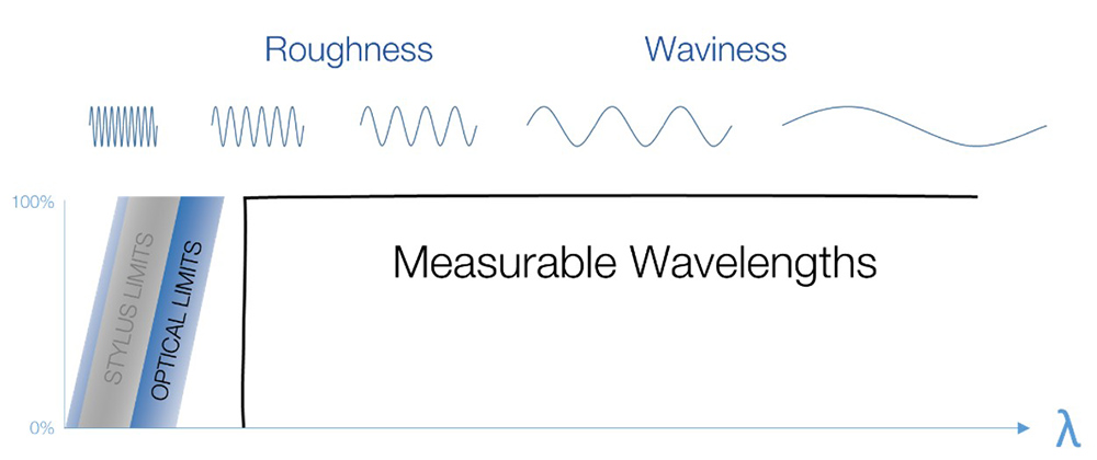
The “measurable” wavelength domain depends on the instrument.
When we are assessing stress-causing valleys, the short wavelength features are extremely important. We have to carefully consider how these features are being detected and reported.
Since instrument limits vary from system to system, we apply a mathematical “short filter” to establish a common, reproducible wavelength band of interest. Using a short filter can reduce the variation between instruments with differing lateral resolutions.
A short filter is defined both by the cutoff wavelength and by the type of filter used. Cutoff wavelengths of 2.5 µm or 8.0 µm are typical. For stylus systems, the Gaussian filter type (ISO 16610-21) is most commonly used. For many optical systems, Robust filters (ISO 16610-71,72) are preferred.
After applying the short filter to a profile or a surface dataset, the resulting dataset is called the “primary profile” or “primary surface.”
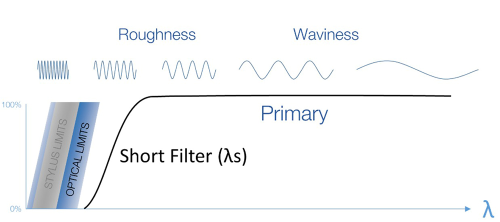
The short filter establishes a reproducible wavelength domain.
Changing the cutoff wavelength for the short filter will change the shape of the features of interest, as in the image below. Because the filter type and cutoff greatly affect the measured values, this information should always accompany any reporting of measurement results. Without filtering information, it can be very difficult to reproduce the reported values.
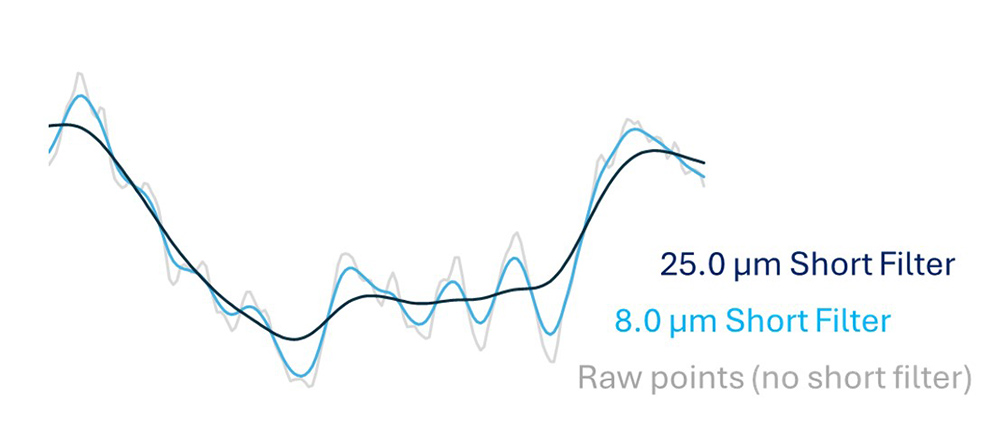
Increasing the short filter’s cutoff wavelength increases the smoothing.
Peak considerations
As we saw earlier, the closing filter mathematically applies a disk/ball to the measured profile or surface. If the ball encounters a sharp peak, large voids may be artificially created on either side of the peak, which can lead to misleading results. In fact, the deepest voids may be related to the sides of these sharp peaks, as shown in red in the image below.
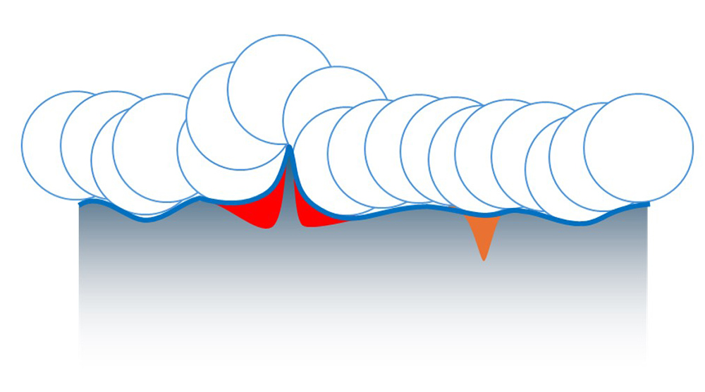
Artificial voids (in red) at the sides of a peak. An actual valley is represented in orange.
One option for minimizing this influence is by using an “alternating sequence” morphological filter, which applies two filters from opposite sides of the surface. In our case we will apply a closing filter to produce a closing profile. We then apply a morphological “opening filter,” which acts like a disk/ball being pushed upward from below the closing profile. The combination of filters results in a more stable reference that is not influenced by extraneous peaks.
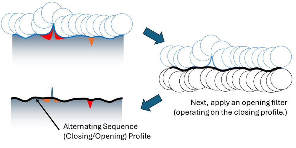
An alternating sequence (closing/opening) filter can produce more reliable results on a surface with sharp peaks.
Putting it all together
Morphological void analysis is a standard part of our OmniSurf (2D/Profile) and OmniSurf3D (areal) surface analysis software.
The example profile below is shown in OmniSurf. The Closing Profile is shown in black on top of the red waviness profile, highlighting extreme voids. A deep. sharp valley has been located, with an effective depth of 3.5 µm relative to a 25 µm closing radius. In this instance, the deepest void is not located at the deepest valleys!
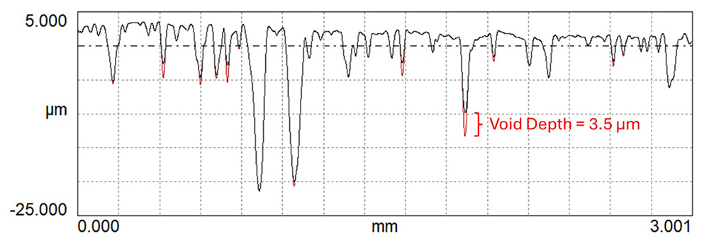
A morphological closing filter (25 µm radius) detects the most severe profile valley.
OmniSurf3D also includes the morphological void depth analysis, for 3D/areal data. In this example data…
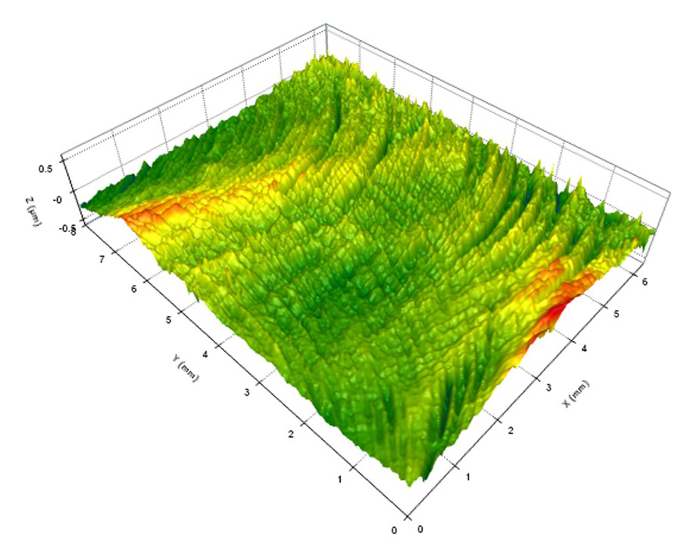
A surface measured via an optical (areal/3D) instrument.
…we can apply a 1.5 mm closing filter to produce this “void surface,” which extracts the deepest, sharp valleys from the relatively random texture.
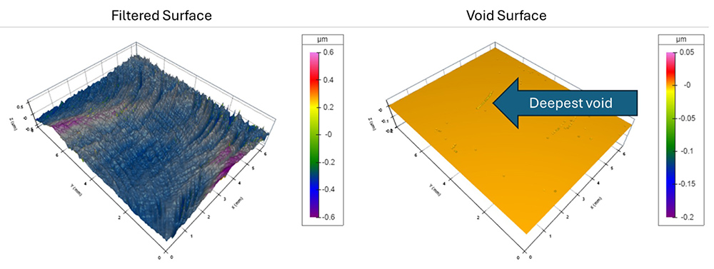
A morphological closing filter (1.5 µm radius) detects the deepest void as the most severe surface feature.
Closing
As we push for better performance from thinner and lighter components, it’s becoming even more essential to properly specify and control the surface texture. We must move beyond simply targeting “average roughness” (Ra) and look instead at the surface features that are actually responsible for potential failures. “Morphological void depth” analysis is just one of the tools that Digital Metrology has developed for exactly this purpose. Through the use of better filtering and a new parameter, our OmniSurf and OmniSurf3D products help you see and understand your surface texture—and improve your component reliability in the process.
Try it out for yourself today!
